
Originally published December 22, 2020, by Bruce Rose, Bel Fuse Inc.
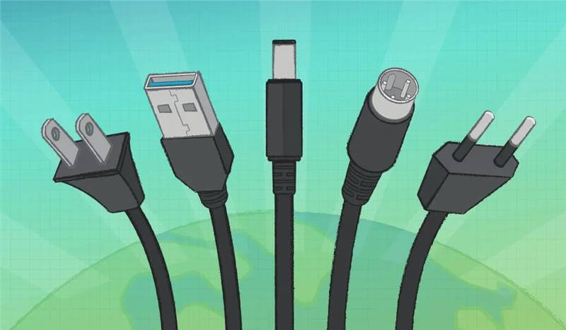
Every external power supply has two connection points to specify: the alternating current (AC) plug that draws power from the wall, and the direct current (DC) connector that delivers power to the end product. AC plugs are tightly standardized by region, so the choices are limited and well defined. DC output connectors offer far more options, and the choice affects current capacity, mechanical retention, and compatibility with the end product.
This article focuses on single-phase AC-DC wall plug and desktop adapters. It covers AC wall plugs and power cords, the appliance inlets used on desktop adapters, and the three most common families of DC output connectors: barrel, Deutsches Institut für Normung (DIN), and Universal Serial Bus (USB) connectors.
AC Wall Plugs and Cords
AC wall plug selection comes down to two questions. First, in which regions or countries will the power supply be used? Second, does the application require two conductors or three conductors?
Most countries have well-defined plug and socket combinations, voltages, and frequencies. Because wall voltages are standardized, AC plugs are rated with sufficient insulation for those voltages. Maximum current ratings are also standardized, and different ratings often use physically different contacts so that mismatched plugs and sockets cannot be mated.
A wall plug adapter has an integrated plug, while a desktop adapter connects to the wall through a power cord. Many desktop adapters use a detachable cord that plugs into a standard AC inlet on the adapter case. Changing the cord adapts the same supply to a different region. Some wall plug adapters offer the same flexibility through interchangeable AC blades.
Plug Types by Region
The International Electrotechnical Commission (IEC) groups plug and socket types by letter designation, such as Type A, Type C, and Type G. This grouping is useful, but it does not capture every regional variation.
Type A plugs, used in North America, Central America, and Japan, illustrate the point. North American Type A plugs are usually polarized, with a wider neutral blade. Japanese Type A plugs often use two blades of the same width. As a result, a Japanese plug typically fits a North American socket, but a polarized North American plug does not always fit a Japanese socket. For a country-by-country reference, see the World Plug and Input Voltage Guide.


Two-Conductor Versus Three-Conductor
In most markets, single-phase AC power is delivered through three conductors, although not every application uses all three. Two conductors carry power. The third is a Protective Earth (PE) conductor, also called Frame Ground (FG) or safety ground, which provides added protection from dangerous voltages.
Modern two-conductor power supplies are built with enough insulation to be safe without the ground conductor. Desktop adapters are available with either two-conductor or three-conductor AC inputs, while wall plug adapters use two-conductor inputs. For more detail, see Insulation, Isolation, and Working Voltage and What Is the Difference Between Class 2 and Class II Power Supplies.
Line and Neutral Versus Line 1 and Line 2
In single-phase AC applications, the power-carrying conductors are labeled either Line and Neutral, or Line 1 and Line 2. The Neutral conductor is intended to sit close to local ground potential, so it is sometimes viewed as the “safer” conductor.
The North American Type A plug uses a wider blade for Neutral and a narrower blade for Line, and matching slots in the socket let the load identify each conductor. Many other plugs, including the Japanese Type A plug described above, can be inserted with Line and Neutral reversed. For this reason, most loads designed for international markets do not distinguish between the Line and Neutral inputs.
When Line 1 and Line 2 are used, the two conductor voltages are often balanced relative to ground, and no Neutral conductor is present.
AC Inlets for Desktop Adapters
Most desktop adapters with detachable cords use an appliance inlet defined by IEC 60320. The standard pairs each cord connector with a matching inlet, identified by a “C” number. The inlet on the adapter carries the even number, and the mating cord connector carries the odd number one below it.
The inlet choice sets the number of conductors and the current rating of the AC connection. It also determines which regional cords can ship with the adapter.
| Adapter Inlet | Mating Cord Connector | Conductors | Typical Rating | Common Use |
|---|---|---|---|---|
| C8 | C7 (“figure 8”) | 2 | 2.5 A | Low-power desktop adapters without a ground |
| C6 | C5 (“cloverleaf”) | 3 | 2.5 A | Grounded desktop adapters, such as laptop-style supplies |
| C18 | C17 | 2 | 10 A (IEC); 15 A (UL) | Higher-power desktop adapters without a ground |
| C14 | C13 | 3 | 10 A (IEC); 15 A (UL) | Higher-power grounded desktop adapters |
Table 1: IEC 60320 Appliance Inlets Commonly Used on Desktop Adapters
Because the cord is detachable, one adapter design can serve many markets by pairing the same inlet with region-specific cords.
DC Power Connectors
DC output connectors are far less uniform than AC plugs, and many non-standard designs exist. This article covers the three families most often specified on external adapters: barrel, DIN, and USB connectors.
| Connector Family | Governing Standard | Strengths | Limitations |
|---|---|---|---|
| Barrel | IEC 60130-10; JEITA RC-5320A | Low cost; no orientation required | Limited current; no retention unless locking |
| DIN (4-pin power) | IEC 60130-9 | Higher current; durable; locking option | Larger; must be oriented to mate |
| USB | USB Implementers Forum (USB-IF) specifications | Compact; USB-C negotiates voltage and current | Type-A limited to 5 VDC; Type-A must be oriented |
Table 2: Comparison of DC Output Connector Families
Barrel Connectors
Barrel connectors are the most common DC power connector. They are inexpensive to manufacture because of loose mechanical tolerances, and they mate in any rotational orientation.
A barrel plug is built from concentric metal sleeves separated by an insulator. The inner diameter, outer diameter, and barrel length each come in several standard sizes, so the design engineer must specify all three.

The mating barrel jack has a center pin that fits inside the plug’s inner sleeve, usually with loose clearance, and a cantilevered spring that contacts the outer sleeve. When the plug is inserted, the spring presses against the outer sleeve and forces the center pin against the inner sleeve. Plug and jack dimensions must be matched to achieve both the intended mechanical fit and a reliable electrical connection.


Retention and Current Limits
The fit between the jack’s center pin and the plug’s inner sleeve is not tightly specified, and neither is the spring force against the outer sleeve. As a result, insertion and retention forces vary widely between plug and jack combinations. A standard barrel connector has no mechanical latch, so it can separate unintentionally. Locking barrel connectors, available with threaded or twist-lock features, solve this problem.

The current rating of a barrel connector depends on contact force and contact area at the spring and at the center pin. Light contact forces and small contact areas limit how much current a barrel connector can carry.
Common Barrel Connector Sizes
Barrel sizes are described by outer diameter (OD) × inner diameter (ID). IEC 60130-10 defines a set of barrel connector dimensions, and the RC-5320A standard from the Japan Electronics and Information Technology Industries Association (JEITA), formerly the Electronic Industries Association of Japan (EIAJ), assigns specific sizes to specific voltage ranges to prevent mismatched connections. The two most widely used sizes are 5.5 × 2.1 mm and 5.5 × 2.5 mm. Table 3 lists common sizes with typical current ratings. Ratings vary by manufacturer and jack design, so always confirm them on the connector datasheet.
| Size, OD × ID (mm) | Standard | Rated Voltage Range | Typical Current Rating | Notes |
|---|---|---|---|---|
| 5.5 × 2.1 | Common industry size | Not specified | 2.5 A ~ 5 A | Most widely used size |
| 5.5 × 2.5 | Common industry size | Not specified | 2.5 A ~ 5 A | Easily confused with 5.5 × 2.1 mm; the smaller pin mates but contacts poorly |
| 3.5 × 1.35 | Common industry size | Not specified | 1 A ~ 2 A | Compact, low-power devices |
| 4.0 × 1.7 | JEITA RC-5320A (EIAJ-02) | 3.15 V ~ 6.3 V | Up to 2 A | Japanese market devices |
| 4.75 × 1.7 | JEITA RC-5320A (EIAJ-03) | 6.3 V ~ 10.5 V | Up to 2 A | Japanese market devices |
| 5.5 × 3.3 | JEITA RC-5320A (EIAJ-04) | 10.5 V ~ 13.5 V | Up to 3 A | Japanese market devices |
| 6.5 × 4.4 | JEITA RC-5320A (EIAJ-05) | 13.5 V ~ 18 V | Up to 3 A | Japanese market devices |
Table 3: Common Barrel Connector Sizes and Typical Current Ratings

Polarity
By convention, the outer sleeve is ground or negative and the inner conductor is positive, a configuration known as center-positive. If the outer sleeve touches an exposed conductor, that conductor is connected to ground rather than to a live voltage. Not every product follows this convention, so some devices use a center-negative configuration. Always check the polarity symbol on the product label.

Straight Versus Right-Angle Plugs
A straight plug, with the cord in line with the connector, is the most common configuration. It is easy to manufacture and easy for the user to align. A right-angle plug has two advantages. It keeps the cord close to the chassis, which reduces the product’s overall footprint. It also improves retention, because tension on the cord creates a torque on the connector that resists disengagement. For further strain relief, the cord can be secured under a hook or latch on the product case so that cord tension never reaches the plug.

DIN Connectors
DIN power connectors have four pin or socket contacts inside a circular housing. They were originally defined by the German standards body Deutsches Institut für Normung and are now defined by IEC 60130-9. Power DIN connectors are used in moderate-power applications where a barrel connector cannot carry the required current.
Power DIN and signal DIN connectors are often confused. There is no absolute definition of a power DIN connector, but by convention it has four contacts spaced approximately 90 degrees apart around the center. Detailed pin dimensions can be difficult to find, but 4-pin DIN power plugs and jacks can generally be assumed to mate correctly. Like barrel connectors, power DIN connectors are available with a threaded locking feature.

USB Connectors
USB connectors were developed to carry both DC power and digital signals. Broad adoption of the USB voltage level and connectors has also made them popular for power-only applications.
USB Type-A
USB Type-A supplies are used in applications requiring 5 VDC, typically at load currents of up to about 2 A depending on the charging scheme. Smaller Mini-B and Micro-B connectors belong to the Type-B family and appear on the device end of many Type-A cables. Type-A and Type-B connectors mate in only one orientation, so the user must identify the correct orientation visually or by trial.
Many electronic products use USB jacks to accept 5 VDC input. For this reason, use Type-A plugs only on power supplies with a 5 VDC output, so that products expecting 5 V from a USB connector are not damaged.
USB Type-C (USB-C)
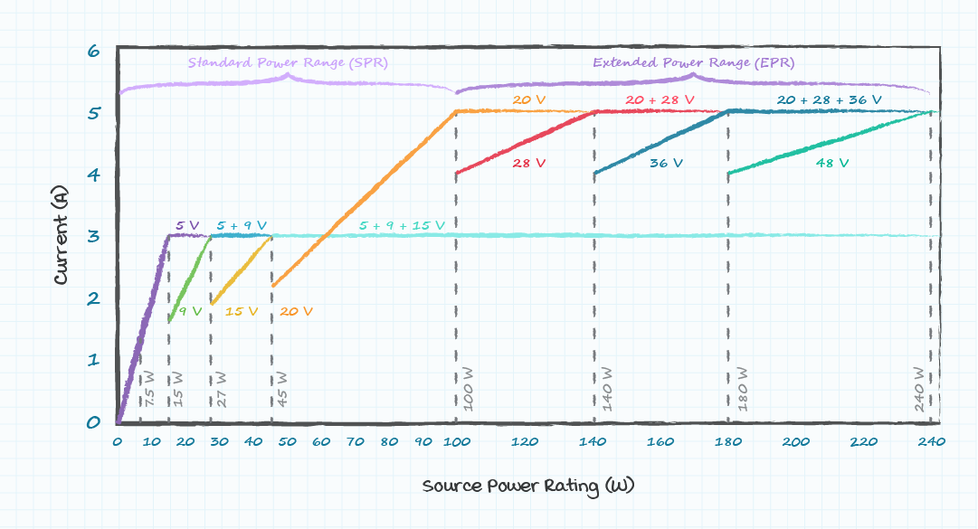
USB-C is more compact than earlier connectors and mates in either orientation. Without power negotiation, a USB-C source can supply 5 V at up to 3 A (15 W). With USB Power Delivery (PD), the supply and the load negotiate a higher voltage and current.
| USB PD Power Range | Fixed Voltages | Maximum Power | Notes |
|---|---|---|---|
| Standard Power Range (SPR) | 5 V, 9 V, 15 V, 20 V | 100 W (20 V at 5 A) | Currents above 3 A require an electronically marked (e-marked) cable |
| Extended Power Range (EPR), USB PD 3.1 | Adds 28 V, 36 V, 48 V | 240 W (48 V at 5 A) | Requires EPR-rated e-marked cable and EPR-capable source and load |
Table 4: USB Power Delivery Power Ranges
USB PD also defines the Programmable Power Supply (PPS) mode, which lets the load request fine voltage steps within the SPR range. For more on PD and PPS, see USB Type-C, Power Delivery, and Programmable Power Supply.
USB-C is quickly becoming the default power input on portable electronics. In the European Union, Directive (EU) 2022/2380 requires USB-C charging ports on many portable devices from December 28, 2024, and on laptops from April 28, 2026. Designers of supplies for these products should plan around USB-C with PD rather than Type-A. For more on the EU requirements, see USB Type-C and Power Delivery Explained.

Specifying Power Supply Connectors
Connectors must be specified alongside the electrical ratings of any external power supply. AC input connectors are well standardized, so the choice is limited to the target markets and power level. DC output connectors are much less standardized, which leaves the designer with more decisions to make.
When specifying the DC output connector, confirm the following:
- Electrical rating. The connector must be rated for the supply’s output voltage and current, with margin.
- Mating dimensions. Barrel plugs need outer diameter, inner diameter, and barrel length specified to match the product’s jack.
- Polarity. Center-positive is the convention, but the supply must match the load and the label must state it.
- Retention. Consider locking or right-angle plugs where accidental disconnection is a risk.
- Voltage compatibility. Use USB Type-A plugs only on 5 VDC supplies, and use USB-C with PD when higher voltages are needed.
- Target markets. Select the AC plug, interchangeable blades, or inlet and cord set for each region where the product will ship.
Bel Fuse Inc offers standard barrel, EIAJ, and USB output plug options, interchangeable wall plug blades for multiple regions, and custom plug and cord modifications on its wall plug and desktop adapters. Contact Bel sales for help selecting the right input and output connectors for your design.
Frequently Asked Questions
What Are the Most Common Power Adapter Plug Types?
On the AC input side, plug types are set by region and grouped by IEC letter designation, such as Type A in North America and Type C across much of Europe. On the DC output side, the most common types are barrel, 4-pin DIN, USB Type-A, and USB-C connectors.
What Is the Difference Between 5.5 × 2.1 mm and 5.5 × 2.5 mm Barrel Plugs?
Both have a 5.5 mm outer diameter, but the inner sleeve diameter differs. A 5.5 × 2.1 mm plug will not fit a jack with a 2.5 mm center pin. A 5.5 × 2.5 mm plug will often fit a jack with a 2.1 mm pin, but the loose fit can cause an intermittent connection. Always match the plug to the jack specification.
What Does Center-Positive Mean?
Center-positive means the inner conductor of a barrel connector carries the positive voltage and the outer sleeve is ground or negative. It is the most common convention, but center-negative products exist. The polarity symbol on the product label shows which applies.
Can a USB-C Power Supply Power a Device With a Barrel Jack?
Only through an adapter or cable that negotiates the correct voltage with the USB-C supply. A USB-C supply outputs 5 V until the load requests a higher voltage through USB PD, so a simple passive adapter supplies only 5 V.
How Much Power Can a USB-C Connector Deliver?
Without power negotiation, USB-C supplies up to 15 W (5 V at 3 A). With USB PD Standard Power Range, it supplies up to 100 W (20 V at 5 A). With USB PD 3.1 Extended Power Range, it supplies up to 240 W (48 V at 5 A), provided the source, load, and cable all support it.
When Should a Power Supply Use a Three-Conductor AC Input?
A three-conductor input adds a Protective Earth connection. It is required when the end product relies on a ground connection for safety or performance (Class I). Supplies with sufficient insulation (typically double or reinforced) can safely use a two-conductor input (Class II).
Featured Products


Related Blogs

Blog Post
What the EU Cyber Resilience Act Means for Rail and Industrial Power Electronics
Learn which rail and industrial power supplies need to be redesigned for the EU Cyber Resilience Act.
Read Blog Post
Blog Post
2.5GBASE-T and 5GBASE-T: Getting Multi-Gigabit Speeds from Existing CAT5e/CAT6 Cables
Unlock multi-gigabit speeds over existing CAT5e/CAT6 cabling with IEEE 802.3bz and Bel ICMs.
Read Blog Post
Blog Post
Ruby Efficiency – What the New 80 PLUS Tier Means for Front-End Power Supplies and Data Centers
Find out how 80 PLUS Ruby raises the efficiency standard and what it means for your next power supply design.
Read Blog Post