
Now that the USB-C EU regulation has come into force, new products that are portable in nature with charging capabilities need to use USB-C cables and connectors, to reduce e-waste while also unifying cable and connection standards. While many have hailed the new laws as progressive, critics of the policy worry that having devices with different power requirements on the market could lead to confusion in the design space. What exactly is the USB C standard, how does it relate to power delivery, and what should engineers watch out for when designing USB-C applications?
USB – A Brief History
Of all the bus protocols to have ever been conceived, none has been as impactful as USB. Before the era of USB, communication between two different devices could be achieved using several different industrial standards, but by far the most common were serial and parallel ports. Serial ports, which transmit data bit by bit, were ideal for low-speed data transfers (in the order of 100 kbps ), and if combined with large voltages (such as +/- 12 V), could be used across significant distances.
On the other hand, parallel ports provide data bits in parallel (typically 8-bits), giving them a speed advantage over serial ports. However, due to the large size of the cable and connector for these ports, they were seldom used with large local devices, such as printers and machinery.
When it came to keyboards and mice, the mighty PS/2 connector took the crown as the industry standard. Despite the fact its origins date back to the original IBM PC System 2, it is still found in computers today (gamers often prefer this port due to the low latency associated with PS/2 keyboards).

These various bus protocols and their respective connectors were perfectly adequate during the early years of personal computers, when entire operating systems could fit on a single 1.4 MB floppy disk and the hardware configuration of a computer setup was rarely changed after it was setup.
However, as computers became more advanced, and more importantly, as portable devices became digital, there needed to be a practical method to connect these devices together. Serial ports were too slow, parallel ports were too big, and no one could agree on an industrial standard for connectivity.
To solve this problem, a group of intelligent like-minded individuals from major tech companies (including Compaq, IBM, Intel, Microsoft, and NEC) came together and laid out the foundations for what became the Universal Serial Bus, or USB for short. By creating a standard that everyone could adopt, devices would not only be able to connect to any machine with a USB port, but also be hot pluggable (not requiring a reboot when plugged in). All this made it simpler to connect new devices together.
The first USB standard, called USB 1.0, utilised a bus voltage of 5 V, a maximum current draw of 500 mA, and data speeds of up to 1.5 Mbps for low bandwidth devices and up to 12 Mbps on full speed. While the increased speed was highly appreciated by engineers (that and the USB demonstration by Microsoft which resulted a BSOD live), it was the power capabilities of USB that engineers gravitated towards most.
The integration of rechargeable batteries expanded the role of USB cables, allowing them to provide power to devices rather than merely communicate data. It didn’t take long for engineers to take full advantage of USB, trying to squeeze out every possible milliwatt the configuration could offer.
Recognising this, the USB Foundation released USB 2.0 in April 2000, which not only improved the maximum speed to 480 Mbps, but also allowed for as much as 1.5 A to be drawn when utilising the battery charging specification. This higher power capability allowed for more power-hungry devices to not just charge over USB, but even use USB as its primary power source.
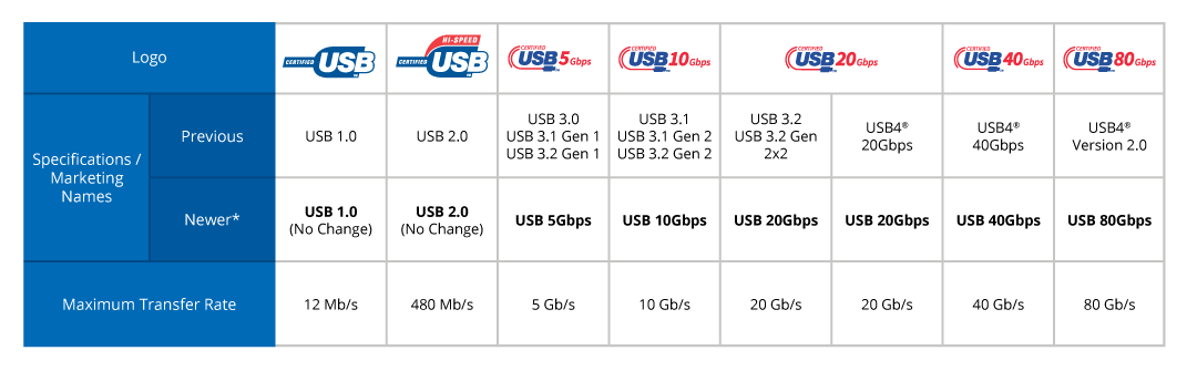
Again, engineers developed more advanced devices, with faster data rates, smaller sizes, and higher charging currents, all of which required the USB foundation to change the specification to accommodate these requirements. After numerous iterations and changes, state-of-the-art USB devices under USB 4 2.0 can see data transfer rates up to 80 Gbps and powers reaching 240 W.
What Exactly is USB Power Delivery (PD)?
With each incremental improvement in USB, the ability for devices to draw more voltage and current introduces a serious issue that, if not handled correctly, could lead to devastating consequences.
As USB is a universal standard, all USB ports must provide the same 5 V voltage by default. When operating at this voltage, providing a few watts of power is no issue due to the low currents involved. However, considering that new devices, such as laptops and quick chargers, want to be able to take as much as 200 W of power, trying to force 40 amps of current down a small USB cable will undoubtedly end in a total disaster, with overheating cables, melting plastic, and electrical fires all being virtually guaranteed.
To get around this high current issue, the voltage being provided by the USB port can be significantly increased, which in turn reduces the current in the wire, keeping the cable cool. While this works extremely well for power hungry devices, standard 5 V USB devices would be instantly destroyed should they ever experience such a bus voltage, which is why it is critical that these higher voltage levels are only used after the host and connected device have properly negotiated their power demands.
This method of power negotiation was introduced by the USB Foundation in 2012, called Power Delivery, and can provide voltages up to 48 V and 240 W of power. This mechanism, if followed correctly, ensures that legacy devices are never exposed to such high voltages, while ensuring that modern devices can take full advantage of PD.

Why Was USB Programmable Power Supply (PPS) Introduced?
There is no doubt that USB Power Delivery provides engineers with plenty of opportunities and helps solve numerous power challenges (such as external displays, laptops, and quick chargers). However, even with all the features that PD offers, there are several drawbacks which can make designing devices complex.
By far the biggest issue is that while PD is ideal for high-power devices, it suffers in devices with internal batteries. The primary reason for this is that most battery technologies in use are lithium based, which means that they have extremely particular charging cycles.
For example, these batteries need to start out on a slow pre-charge to prep the battery, which is then followed by a high current charge, and when the battery reaches around 80% of its capacity, the charging current needs to be significantly dropped. While this charging current can be managed via a battery charging controller, the need for additional electronics introduces additional component counts to a device, resulting in more failure points and a larger design.
Another disadvantage to USB PD is that because there is no reliable way to quickly change the voltage and current, the bus voltage can be left at high levels for extended periods of time. This not only contributes to gradual wear on connectors through corrosion but can also induce sparking when disconnecting connectors (which in turn degrade contacts).
To get around these issues, USB Programmable Power Supply (PPS) was introduced, which allowed devices to negotiate higher voltage and powers from a host and control these values in real-time in small increments. With 20 mV steps in the output power, devices can not only control the voltage, but also the corresponding current that is drawn, thereby eliminating the need for additional charging circuits.
USB 3.0 vs. USB-C
When it comes to USB 3.0 and USB-C, one common misunderstanding is that the two systems are interchangeable. While this belief is inaccurate, there is a logical reason why these two have been misunderstood.
USB 3.0, which was introduced in 2008, defines the electrical properties of the bus, including its voltage current, power, and speed. However, due to the extremely high power and bandwidth capabilities of the protocol, it requires a second set of connections (which can be seen on USB 3.0 ports, typically blue). This need for a special cable meant that all USB cables in existence during its release were incapable of supporting USB 3.0.

To make matters worse, as many portable devices during this time were taking advantage of the small size of micro-USB and mini-USB connectors, none could support USB 3.0 due to the lack of additional connectors (i.e. these connectors supported USB 2.0 only). The extreme popularity of these connectors also meant that manufacturers simply couldn’t deploy USB 3.0 into their designs without making custom cables, something consumers detest.
However, in 2014, the USB-C cable was introduced to the world, which not only supported USB 3.0, but also came with numerous features including the ability to work in either orientation. The USB-C cable’s vastly superior properties saw it rapidly integrated into electronics, and it was around this time that consumers were introduced to USB 3.0. Hence, the confusion between USB 3.0 and USB-C.
What Makes USB-C Such an Excellent Connector Choice?
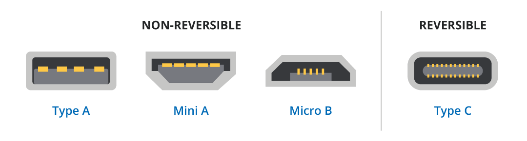
USB connectors come in numerous shapes, sizes, and form factors, and while they all have their own advantages and disadvantages, none come as close to perfection as the USB C connector does. But what exactly makes USB C favoured by manufacturers and consumers alike?
By far the most convenient feature of USB C is that it does away with USB superposition whereby it takes three attempts to insert a USB connector (something which Intel documented very well in a graphic). Simply put, USB-C has no polarity and can be inserted in either orientation.
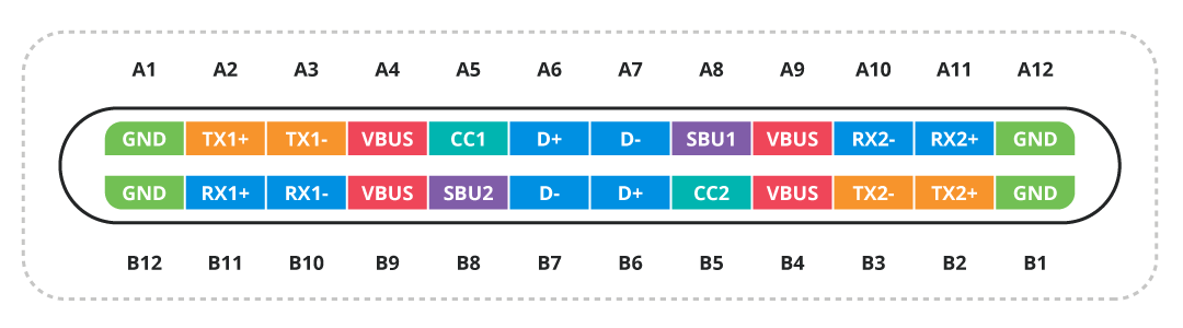
The second major advantage of USB C is that it integrates a greater number of conductors, which not only supports higher power ratings, but also allows for significantly increased bandwidths. Furthermore, the inclusion of additional contacts also allows for hosts and devices to communicate, as well as determine the orientation of the connector.
The small size of USB C also makes it highly desirable to device manufacturers, as PCBs can be significantly reduced in size. Smaller USB ports also allow for more ports to be integrated into the same space, thereby allowing hosts to connect to more devices simultaneously.
The unique mechanical design of USB C, utilizing spring-loaded contacts in the cable, means that USB C ports are less likely to wear down over time, with the cable being easily replaced. Furthermore, the design of USB C also makes it far stronger than previous USB connectors, especially micro USBs.
Another important feature of USB C is that the curved design makes it self-aligning, and therefore easier to insert. This self-aligning capability also reduces mechanical stress on the connector and receptacle, ensuring longevity.
Above all else, the combination of these benefits has made USB C immensely popular amongst manufactures, which in turn has helped reduce the cost of USB cables and connectors via mass production. This widespread use has also helped to fully cement USB C as the gold standard for new USB devices, while also ensuring USB 3.0 support.
What Exactly is the New EU Mandate Surrounding USB-C?
Recognizing the massive amounts of e-waste being generated from cables, the EU introduced new legislation that will require all portable electronic devices (including smartphones, tablets, and other gadgets) to use USB-C as their charging and data port. Not only do these devices need to conform to the mechanical standards surrounding USB-C, but they will also need to conform to the electrical standards.
This doesn’t mean that new devices need to support USB 3.0, but only that they must be able to properly negotiate their power requirements so that attached hosts won’t deliver too much voltage or current. ensuring that all new devices use USB-C will help consumers with regards to cable selection (as only one cable type will be needed) while also eliminating the need for manufactures to provide cables with products.
Another benefit to using standardized cables is that it prevents manufactures from holding a monopoly on proprietary cables. By eliminating this monopoly, not only can consumers make their own decisions on where to source their cables, but other manufacturers can produce their own USB C cables without fear of infringing IP.
Even if the environmental and social benefits of switching to USB-C are ignored, there remains the biggest benefit; it helps to push USB 3.0 onto consumers. The benefits that USB 3.0 and USB-C have over their predecessors is significant, and by encouraging engineers to switch over now, devices supporting high data rates and larger powers will be available sooner.
It is important to note that the new legislation also requires designs to adhere to the standard USB PD protocols if more than 15 W is being used. This means that proprietary USB chargers with unique features cannot be utilized in any way, shape, or form, as they can introduce serious safety risks to unsuspecting users.
Why Does the EU Mandate Leave Some Engineers Concerned?
Except for a small minority of businesses, the engineering community has welcomed the mandate with open arms. However, while they may agree with the EU’s general position, many engineers recognize that the new mandate introduces some serious concerns.
The primary concern behind the mandate is that there will undoubtedly be devices sold that do not properly conform to USB standards. Even though such a device would be illegal under the new EU rules, that hasn’t stopped hundreds of thousands of non-conforming devices from flooding the market in the past.
In the case of USB 3.0 and USB-C, if non-conforming devices are connected to USB hosts capable of delivering high voltages and currents, then there is a very real chance of serious damage. However, such dangers could also arise from poorly designed cables and misbehaving hosts; it’s not just the client device that is at potential fault.
Such concerns also extend to legacy devices, which could potentially struggle with new USB host ports and power supplies. Under normal conditions, legacy devices should not cause issues as high-power delivery requires a careful exchange of signals, but should a mistake occur, legacy devices would likely be destroyed by high voltages from a USB 3.0 compliant host.
With respect to the cable, not all USB cables are equal, and cables used to transfer data between phones and computers are not the same as those used to charge laptops. If a poorly designed device tries to draw the full 240 W from a charging port over a $1 cable, the cable will likely overheat and cause serious damage (potentially being a fire risk). As all devices would be required to use USB-C, it may be difficult for users to correctly identify what type of USB-C they require.
Finally, engineers have also pointed out that being forced to use USB-C could stifle innovation. Many advances in technology have come from engineers finding new solutions to problems and then using those solutions to better market their products. For example, IBM’s work on floppy disks allowed machines to transfer data far more easily than cassette tapes, the introduction of the x86 architecture in combination with the IBM BIOS allowed different manufacturers to make compatible machines, and even the USB protocol itself was introduced by engineers looking for new solutions.
How Do Proper USB Implementations Protection Against Potential Damage?
Unfortunately, there is little that can be done regarding the countless non-conforming devices that will undoubtedly find their way to the market, but that doesn’t mean engineers developing high-quality products conforming to USB standards can’t take measures to better protect their devices and those that they connect to.
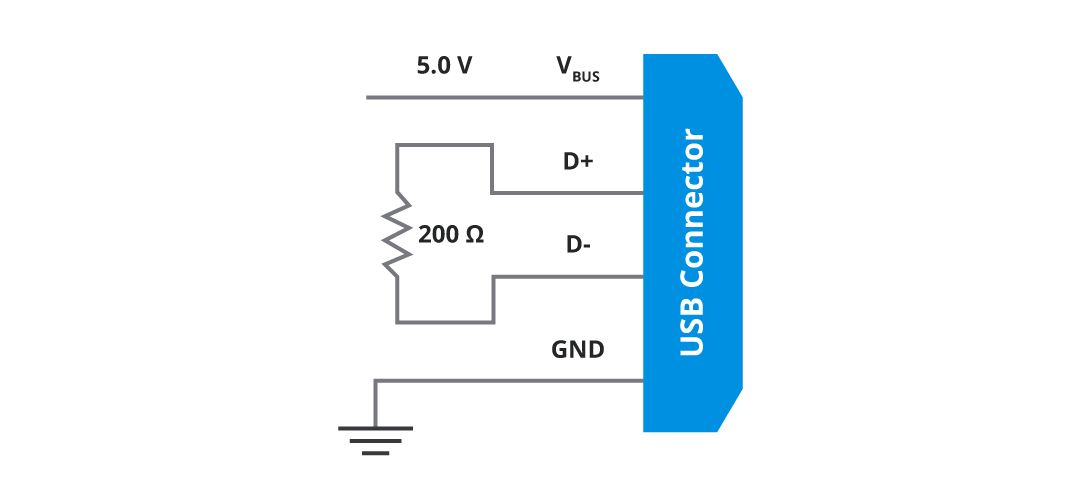
By default, USB ports conforming to USB 1.0 never provide more than 100 mA when a device is first connected (i.e. its enumeration stage). However, during this stage, the host will also monitor the state of various pins to see if more current is being requested. Called “native charging”, devices can utilize special resistor arrangements on the D+ and D- to get up to 500 mA of current when used with a USB 2.0 host, and up to 900 mA for USB 3.0 hosts.
In the case of USB-C ports, power to the port is disabled by default, providing devices and the host with an extra layer of protection. This default power off setting is crucial in protecting devices from large voltages that may have been present on that port from a previous connection.
Once connected, a USB 3.0 host will monitor the USB port CC pins for a connection, and if detected, will initiate standard USB 1.0 protocols. Depending on the configuration of the CC, D-, and D+ pins, a USB 3.0 port will provide up to 900 mA of current without the need for any digital communication.
However, designs needing to exceed the 900 mA limitation will need to integrate USB PD and USB PPS. To do this, the CC pins are used to communicate with the host to negotiate specific power requirements as laid out in USB PD and USB PPS. In such cases, a secondary USB PD chip in both the device and host negotiates this power request.
Some designs (such as those used in proprietary chargers) have avoided PD and PPS due to its complexity and increased system cost, and instead integrated their own messaging protocols and/or circuit configurations. While this can work, it leads to the issue of some USB C cables not working with devices, or some charging ports potentially damaging unsuspecting USB devices that need to charge. Now that the EU has banned this practice, designs looking to exceed 15 W will need to incorporate USB PD and/or USB PPS.
How Can Engineers Help to Mitigate Such Concerns?
To prevent damage to devices, hosts, and cables, it is imperative that the standards as laid out by the USB foundation are followed with no deviation. Devices that attempt to pull more current than what is defined in the various USB standards should be immediately disconnected, and deviations in the voltage and current should be examined with great caution.
The easiest way to ensure conformity is to take advantage of PD and PPS interface chips which will handle all the negotiation and pin connections from the USB-C port. Furthermore, the use of high-quality USB-C connectors is a must due to the potentially high voltage and currents that devices can experience under the USB 3.0 PD and PPS protocols.
While it is possible to wire a circuit to a USB-C port without using PD and PPS, it won’t be allowed to draw more than the 900 mA as stated in the USB 3.0 standards. For devices looking to draw up to 900mA from a host, the cc pins are required to be pulled down with 5.6k resistors. According to some sources, up to 3 A can be drawn if 10k resistors are used, but as this would be out of spec of the USB 3.0 standard, it would likely not be allowed under the new EU mandate (and thus is highly ill-advised).

It is also important to ensure that consumers are aware of the power requirements of their devices, and that not all power cables will be suitable. This could be achieved with the use of warning labels, instructional videos, or even public awareness campaigns for products sold.
But by far the most practical option for engineers looking to mitigate issues arising from USB-C and USB 3.0 is to get their designs USB certified. While there is no need for a license to produce and sell USB compliant devices, only those that have been certified can carry the USB logo, which informs consumers that the marked device is both safe to use and guaranteed to work with all USB protocols.
USB's Continued Importance
The brilliance that is USB cannot be understated, empowering billions of devices globally. The ability for two devices from entirely different platforms and architectures to communicate using a common cable is truly amazing, and if it wasn’t for USB, the world would still be using antiquated communication methods that would likely struggle to work together (that or be beholden to monopolies controlling proprietary cable technologies).
As with all technology, USB continues to advance with each passing year, and it won’t be long before USB 4.0 becomes mainstream, offering speeds up to 80 Gbps (something which is only currently seen in datacentre networks). Furthermore, there is no doubt that USB-C will play a critical role, thanks to its non-polarised deign, strong mechanical properties, and adoption by industry leaders as the de-facto cable of the future.
However, now that USB PD and PPS is here to stay, it is imperative that engineers carefully considered how their devices interact with USB hosts, and what power supplies they utilize. Just because a power supply can provide 200 W over a USB cable doesn’t make that supply suitable; if connected to a USB 1.0 device it may very well cause serious damage to the device, the cable, and even itself.
Instead, engineers must ensure that any power delivery system over USB conforms to the USB standards. The use of dedicated interface chips that support PD and PPS will not only ensure USB devices conform to the new EU regulations but will provide consumers with reliable USB devices that will last throughout the next decade.

.jpg)