Abstract
The time constant of a railway direct current (DC) power system, the ratio of circuit inductance to resistance, governs how quickly fault current rises toward its prospective value. Railway traction circuits combine high inductance with low resistance, producing time constants far longer than what standard DC fuses are designed and tested for. Under a slow current rise, a fuse element heats gradually and can reach an intermediate state in which its mechanical properties have changed but the circuit has not been interrupted. From that state, the fuse can no longer be relied upon to behave as its ratings predict. This paper explains the mechanism, examines its consequences in service, and defines the additional parameters a specifying engineer must supply to select a fuse that will protect a railway DC circuit reliably.
Key Takeaways
- The time constant of a railway DC circuit, the ratio of inductance to resistance, sets how fast fault current rises. It is a third specification parameter alongside voltage and current.
- Railway traction loops combine kilometers of conductor with deliberately low resistance, producing time constants far longer than the conditions under which standard DC fuse ratings are verified.
- Under a slow current rise, a fuse element can soak into an intermediate state: altered but still conducting, and no longer described by its published curves.
- An element in that state is both more likely to open on normal load and less certain to clear a real fault, so no change of rating recovers predictable protection.
- Specifying a railway DC fuse means characterizing the system, including its time constant range across fault positions, and asking the supplier for evidence at those conditions.
Why a Correctly Rated Fuse Can Still Be the Wrong Fuse
A fuse that is correctly rated for voltage and current can still be the wrong fuse for a railway DC system. This is not a matter of margin or derating. It is a consequence of an assumption built into the ratings themselves: that fault current rises quickly enough for the fuse element to melt and interrupt the circuit in one continuous event. Railway DC circuits routinely break that assumption.
The engineer specifying circuit protection for railway rolling stock, traction power supplies, or onboard auxiliaries typically follows established practice:
- Select a DC-rated fuse.
- Match the voltage rating to the system voltage.
- Size the current rating against the continuous load.
- Confirm that the breaking capacity exceeds the prospective fault current.
Every step is correct, and together they are still not sufficient, because none of them accounts for how fast the fault current will rise.
That rate of rise is set by the system time constant, the ratio of circuit inductance to resistance. Railway DC systems combine long supply runs, high circuit inductance, and low resistance, which makes their time constant far longer than the values used in standard fuse characterization. Under a slow rise, the fuse element does not pass cleanly from intact to open. It can dwell in an intermediate state in which the element metal has already changed but the circuit has not been interrupted, and from that state the fuse no longer behaves as its ratings predict.
This paper explains that mechanism from first principles. It describes how a fuse interrupts a circuit and why railway systems produce the conditions under which that process breaks down. It then examines what the intermediate state does to protective behavior in service, and how purpose-designed railway fuses are engineered to avoid it. It closes with the parameters and questions an engineer should bring to a supplier when specifying protection for a railway DC system.
How a Fuse Actually Interrupts a Circuit
A fuse interrupts a circuit by converting excess electrical energy into heat within a metal element until the element melts. An arc then forms across the gap and is extinguished, leaving the circuit open. Every characteristic printed on a fuse datasheet describes some aspect of this thermal process, and every one of them is measured under defined test conditions.
The element is the engineered core of the device. It is sized so that heat generated at normal load current flows out through the terminations and the surrounding filler as fast as it is produced, holding the element at a stable temperature. In many designs the element carries deliberately narrowed sections that concentrate heating and define where melting begins. When current exceeds the design threshold, heat generation outpaces dissipation and the element temperature climbs. At the melting point the element opens, the current transfers to an arc, and the fuse must extinguish that arc against the system voltage before interruption is complete.
Fuse engineering divides this event into two intervals. The pre-arcing time runs from the onset of the overcurrent to the moment the element melts. The arcing time runs from melting to final extinction. Their sum is the operating time, and the time-current characteristic plots that time against current magnitude. Published curves come in more than one form. Power and industrial fuses are characterized by a minimum melting curve, which corresponds to the pre-arcing interval, and a total clearing curve, which includes the arcing interval. Bel Fuse Inc traditional fuses publish the average melting curve. Reading a datasheet correctly begins with knowing which of these three curves is on the page.
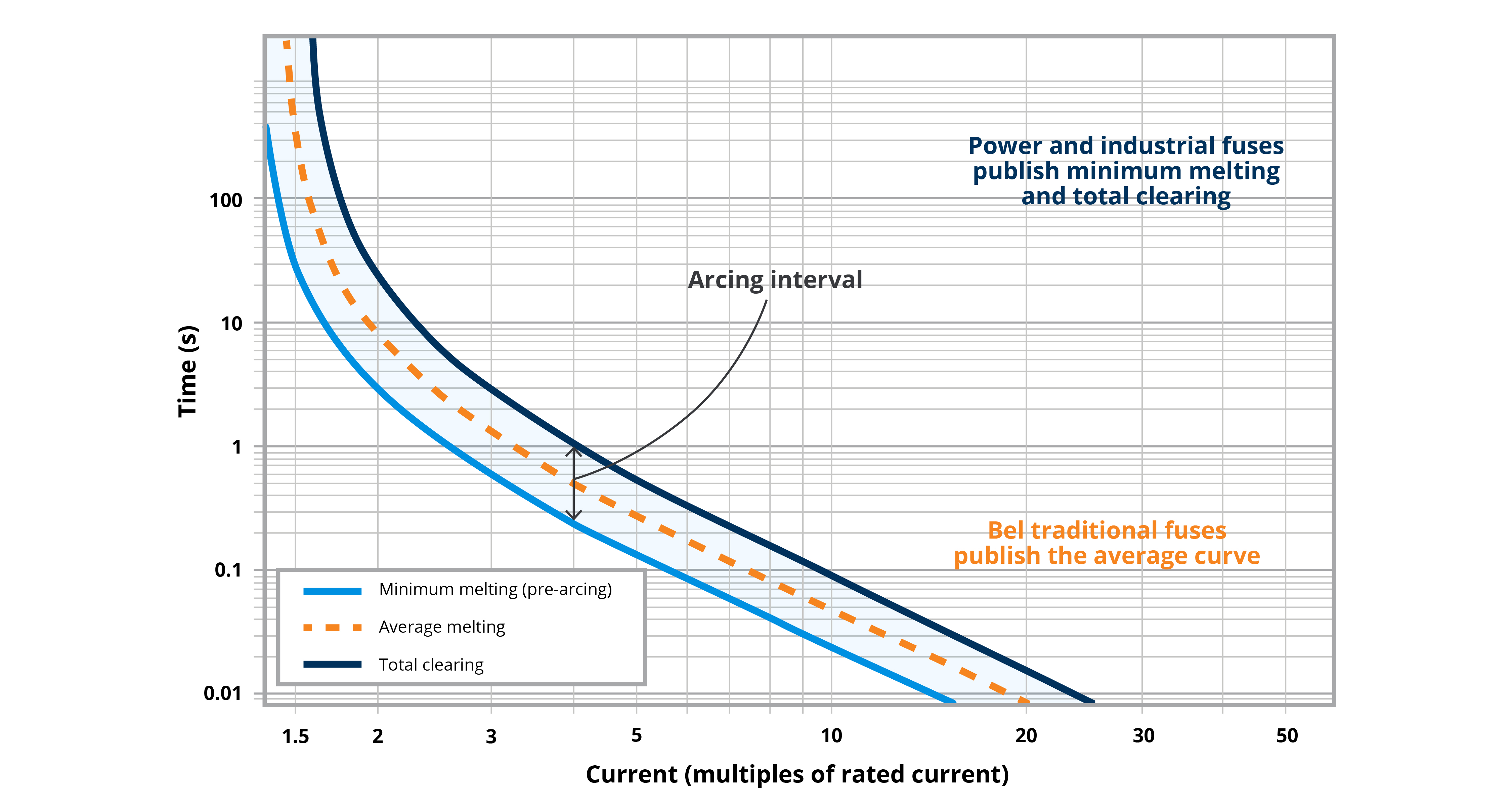
The characteristic rests on an assumption about speed. At high fault currents the element melts in milliseconds, too quickly for meaningful heat to escape, so the process is effectively adiabatic. Engineers describe it as the melting integral, the integral of the square of the current over time.
Here i(τ) is the instantaneous current through the fuse as a function of time τ, and t is the duration of the current pulse. The value the integral takes for a given event depends on the shape of that pulse. Table 1 gives the closed-form expressions for the waveshapes most often used in fuse selection, alongside the shape of each pulse.
| Waveshape | Pulse Description | Melting Integral | Current Pulse |
|---|---|---|---|
| Rectangular / square | Flat current over a defined time | 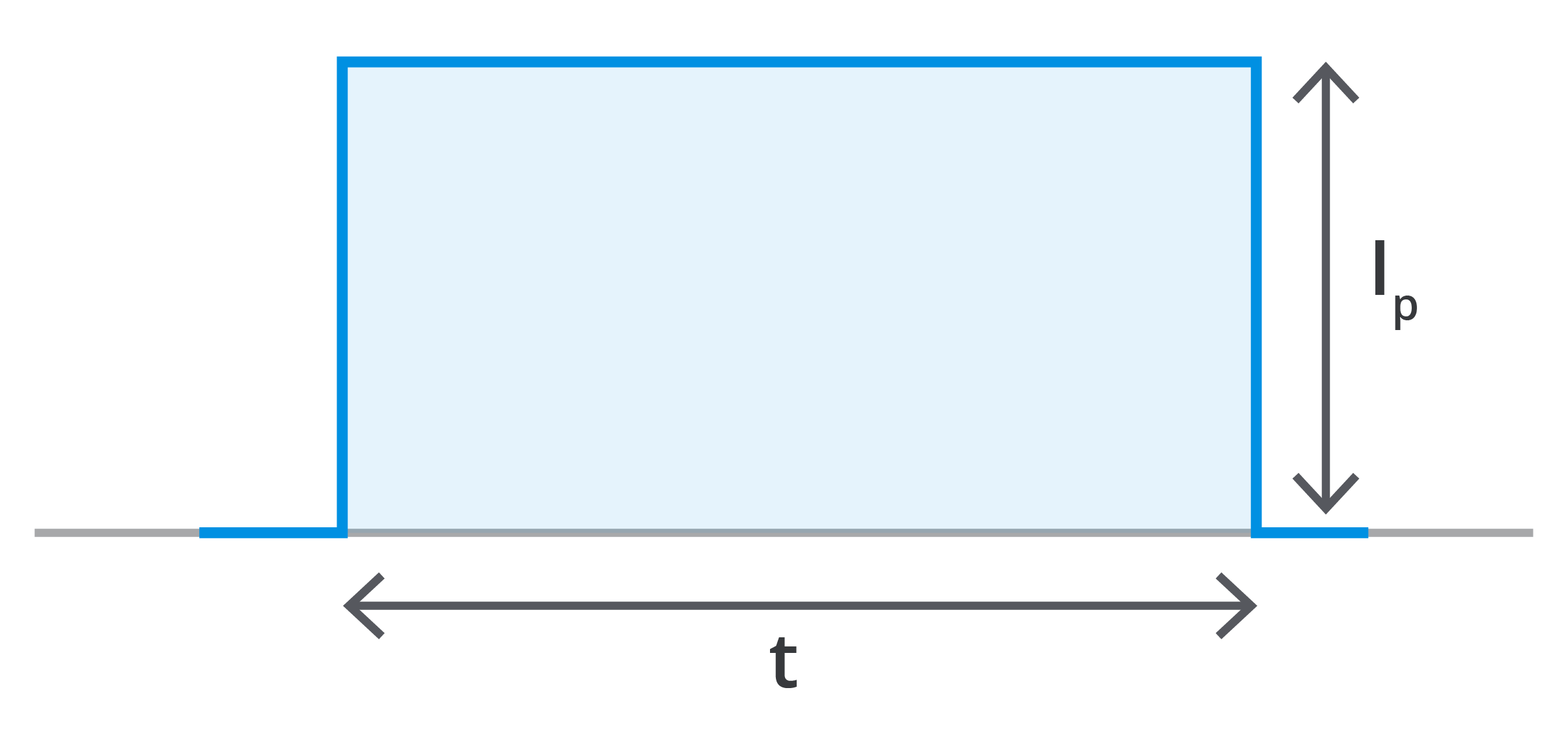 |
|
| Triangular | Linear ramp up and down over a time base | 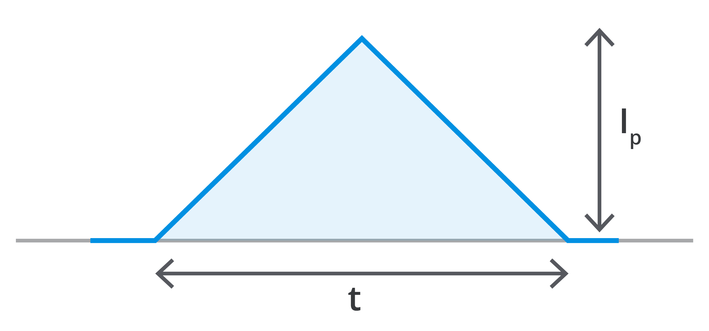 |
|
| Half sine | Single sine pulse over a defined period | 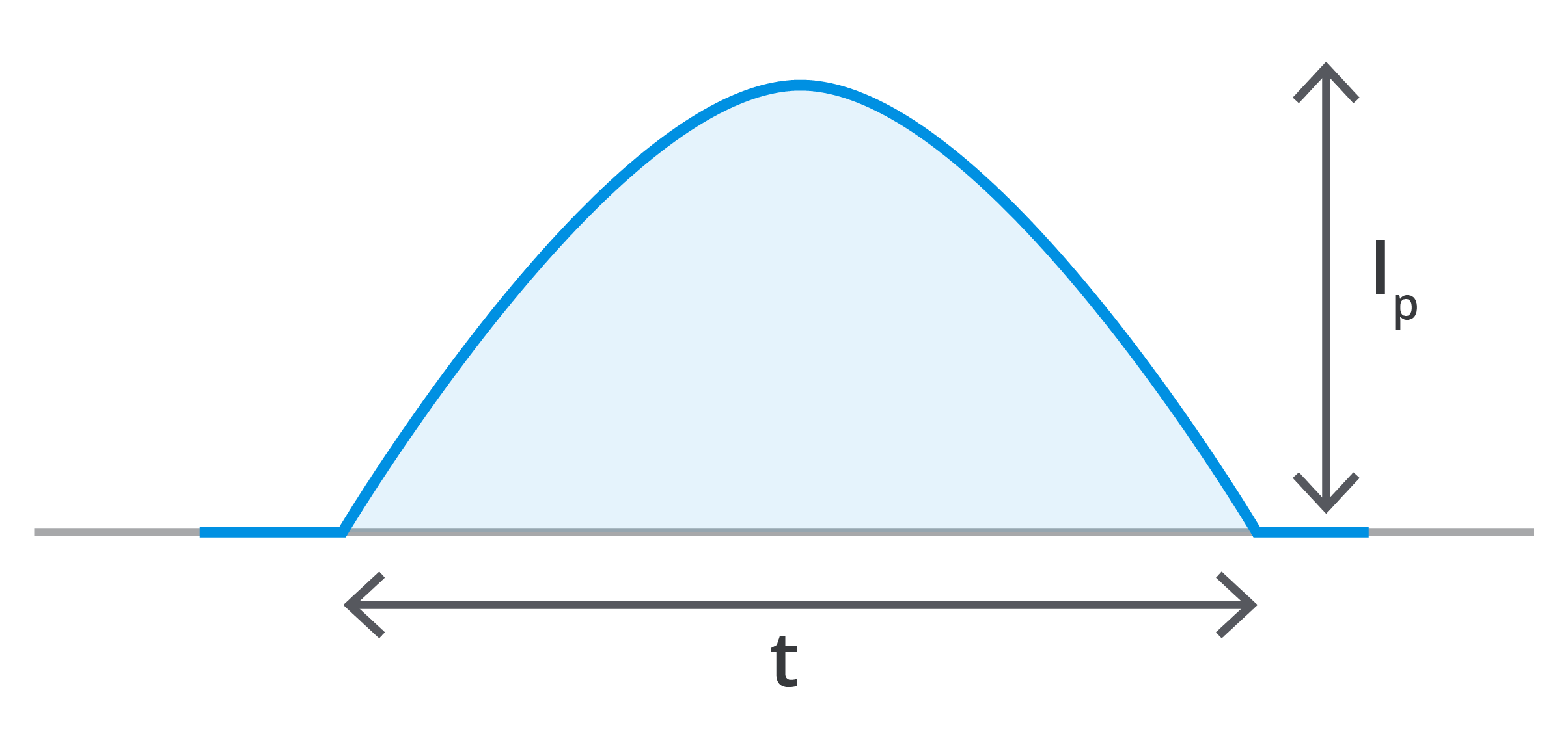 |
|
| Exponential | Inrush surge decaying over a time constant | 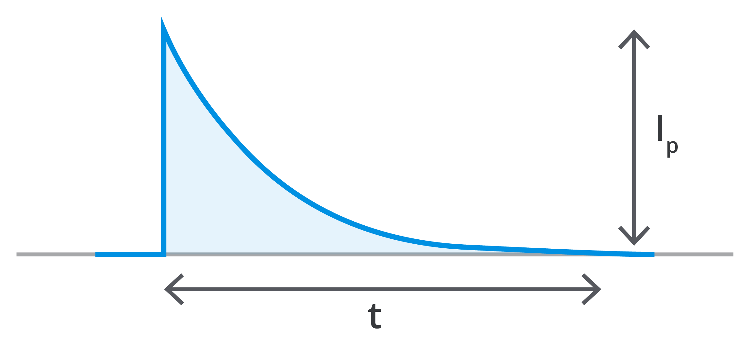 |
Time-current curves and breaking capacity ratings are established in test circuits with a defined rate of current rise, and DC breaking capacity in particular is stated at a specified circuit time constant. The published characteristics therefore describe a fuse whose fault current rises at least as fast as it did in the test circuit. When current rises far more slowly, heat leaves the element during the event itself, and the ratings no longer describe what the element experiences. The next section examines the systems where that happens.
The Time Constant, and Why Railway Systems Are Different
The time constant of a DC circuit is the ratio of its inductance to its resistance, written as L/R and expressed in milliseconds. It describes how quickly current in the circuit approaches its final value.
τ = time constant in seconds
L = inductance in henrys (H))
R = resistance in ohms (Ω)
When a fault occurs, current does not step instantly to the prospective fault level. It rises along an exponential curve, reaching roughly 63% of the prospective value after one time constant and effectively all of it after five.
A circuit with a time constant of a few milliseconds delivers nearly its full fault current at once. A circuit with a time constant ten times longer delivers the same fault as a slow ramp, and for a fuse those are two different events. The difference is not academic: it determines how long the element sits in the region where it is heating without decisively melting.
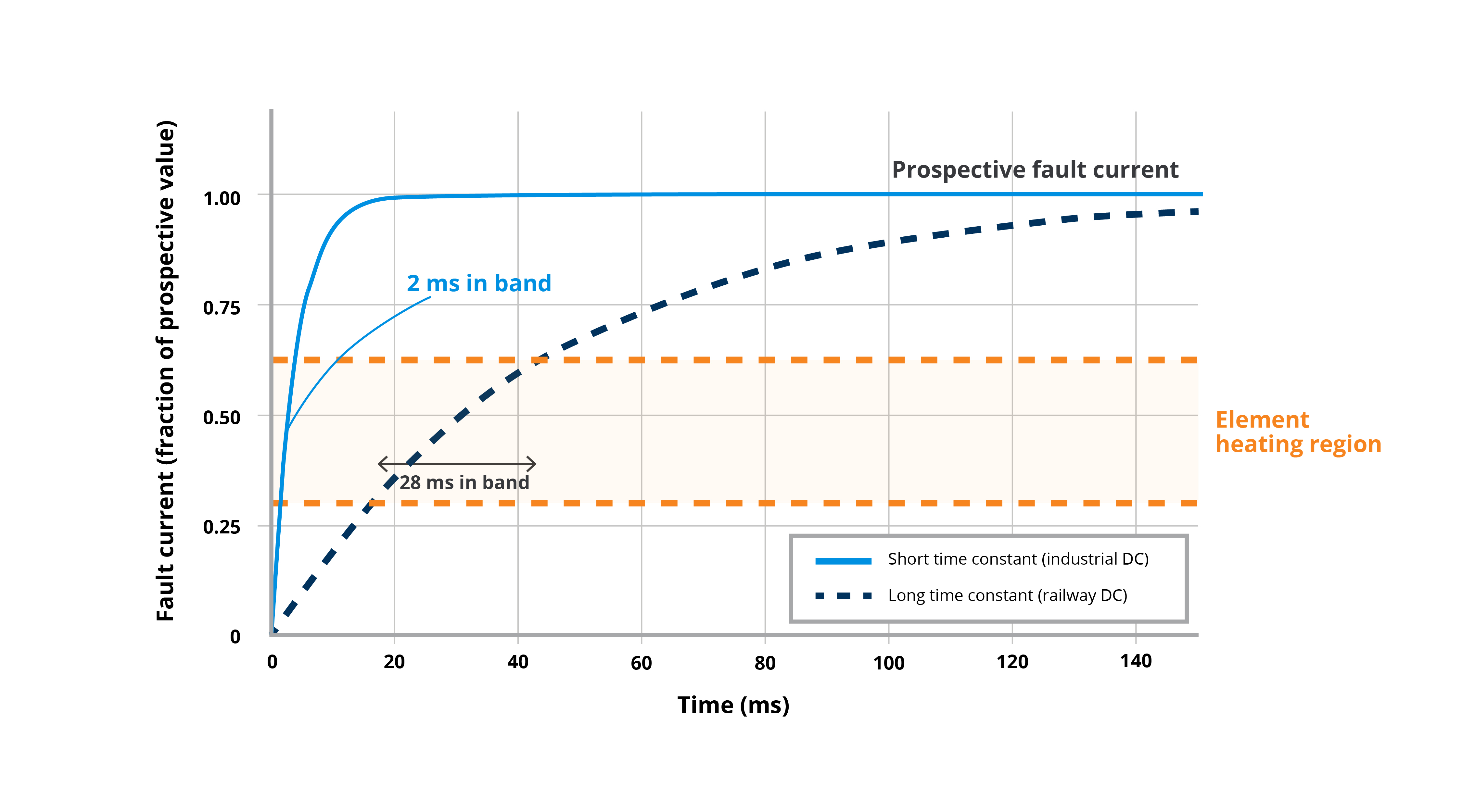
Railway DC systems are inductive by construction. The traction supply loop runs from the rectifier substation through the overhead contact line or third rail to the train and back through the running rails. That conductor loop can extend for kilometers, and it contributes inductance along its entire length. Inductance enters the loop from several places at once:
- The conductor loop itself, which contributes inductance along its full length.
- Smoothing reactors at the rectifier substation, added to filter the DC supply.
- Input filter inductors on rolling stock, ahead of the onboard converters.
At the same time, every part of the supply path is engineered for low resistance, because resistance in a traction circuit is transmission loss. High inductance divided by low resistance is a long time constant, arrived at not through any single design choice but as a structural property of how DC traction power is delivered.
The fault position compounds this. The loop inductance and resistance both depend on where the fault occurs along the line. The time constant of a railway DC system is therefore not a single value but a range, set by the geometry of the installation and the position of the train. A fuse in this environment must be specified against the full range, not a nominal point.
Standard fuse characterization does not cover this territory. DC breaking capacity ratings are established at a stated test circuit time constant, and the values used for conventional industrial DC verification are short relative to what railway traction circuits produce. Table 2 sets the characterization conditions against the conditions a railway installation presents.
| Context | Typical Time Constant | What It Represents |
|---|---|---|
| Board-level DC fuse verification | Under 1 ms | The DC interrupting rating on a surface-mount or cartridge fuse datasheet. |
| Melting integral test circuit | Well under 1 ms | The near-adiabatic condition under which published I²t values are measured. |
| Traction fuse qualification | Roughly 8 ~ 15 ms | The stated verification condition for purpose-built high-speed traction fuse links. |
| Railway DC traction circuit | Tens of milliseconds, reported up to about 100 ms | The range an installation can actually present, varying with fault position. |
The gap spans orders of magnitude. A fuse whose ratings were demonstrated against a fast rise carries no demonstrated behavior for a slow one. The consequences of that gap are the subject of the next section.
The Intermediate State: Where the Failure Mode Lives
A fuse element subjected to a slow current rise can enter a state in which it is neither intact nor open. The metal has absorbed enough heat to change, but not enough, or not in the right place, to melt through and interrupt the circuit. Everything that makes this failure mode dangerous follows from that one fact: the element is altered, and every rating on the datasheet was measured on an element that was not.
The mechanism is a breakdown of the fuse's thermal design intent. Under a fast fault, heating is effectively adiabatic and concentrates at the narrowed sections of the element, which melt first and open the circuit exactly where the designer intended. Under a slow rise, there is time for heat to conduct away from the narrowed sections and spread along the full length of the element. Instead of a sharp local melt, the entire element soaks at elevated temperature. Held near its melting point, the element metal begins to change: it anneals, its grain structure coarsens, and its mechanical strength falls. In element designs that rely on a low-melting-point alloy deposit to define the overload response, sustained heat drives that alloy to diffuse into the base metal ahead of any interruption.
None of this is visible from outside the fuse. The element still conducts. The circuit still functions. But the component is no longer the component that was characterized, and its subsequent behavior cannot be predicted from the published curves. Its effective rating has drifted, its melting behavior has changed, and its mechanical integrity under vibration, a permanent companion in railway service, is reduced.
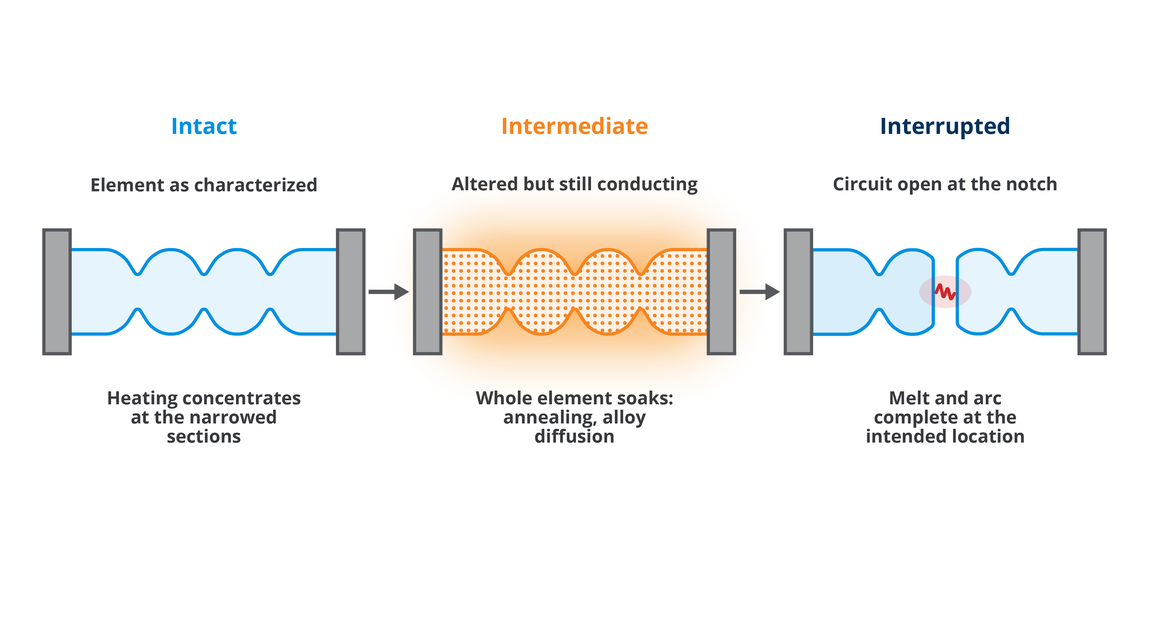
The end point of this progression is the most serious outcome. An element that finally lets go from a degraded state does so under conditions the fuse body and filler were never designed to manage. The arc forms across weakened metal at an uncontrolled location rather than at an engineered narrowed section. When that happens, the assembly can fail violently. The fuse is a device whose entire function is the controlled containment of an interruption, and the intermediate state removes the word controlled.
What this means for the system while the element remains in service, before any such event, is the subject of the next section.
What This Means in Service
A fuse in the intermediate state degrades protection in two directions at once. It becomes more likely to operate when it should not, and less certain to operate when it must. Either consequence alone would be a reliability problem. Together they mean the device can no longer be reasoned about from its ratings at all, because the two failure directions cannot be traded against each other with margin.
The first consequence is nuisance operation. An element that has been thermally degraded has lost part of its current-carrying capacity. A fuse that comfortably carried its rated load when installed may now run hotter at the same load, sit closer to its operating threshold, and open under a normal service condition. A routine start, a converter inrush, or an everyday load step can now be enough to cause the fuse to operate. In railway service the cost of a nuisance operation is not limited to a replacement fuse. It is a train stopped in service, a converter offline, and a maintenance intervention. Repeated across a fleet, it becomes a pattern of unexplained failures that consumes engineering time, because each individual event looks like a defective fuse rather than a systematic misapplication.
The second consequence points the opposite way. The same altered element cannot be relied upon to interrupt a genuine fault promptly. Its melting behavior no longer matches the published time-current characteristic, and the slow-rise conditions that degraded it in the first place remain present for the next fault. A protective device that operates late, or unpredictably, defeats the coordination study built around it. Upstream devices were sized on the assumption that the fuse clears within its published operating time, and that assumption no longer holds.
The combination is what makes the condition dangerous rather than merely inconvenient. A component that is simultaneously too sensitive and not protective enough offers no safe direction in which to add margin. Oversizing the fuse to suppress nuisance operation moves it further from protecting the circuit. Undersizing it to guarantee interruption invites more frequent degradation. The specification problem cannot be solved by adjusting the rating, because the rating is not the parameter that failed. The resolution has to come from the design of the fuse itself, which is the subject of the next section.
How Purpose-Designed Railway DC Fuses Address It
A railway DC fuse resolves the intermediate state problem by being designed to the time constant of the system it protects, not only to the system's voltage and current. The element is engineered so that, across the full range of current rise rates the installation can produce, heating still concentrates where the designer intends and melting still completes rather than stalling. The ratings on a conventional fuse describe how it behaves under assumed conditions; a railway fuse is built so that the railway's actual conditions are the assumed conditions.
Several design variables carry that intent:
- Element geometry, including the profile and placement of the narrowed sections.
- Choice of element material.
- Distribution of thermal mass along the element.
Together these set how the device shares heat between local melting and conduction away from the melt site. For a long time constant, the balance is deliberately shifted so that a slow rise still produces a decisive local melt instead of a whole-element soak. The surrounding filler and the arc management design are sized for the other half of the problem. A highly inductive circuit stores energy in its inductance, and every joule of it must be absorbed by the arc during interruption. A long time constant therefore demands not only an element that melts correctly under a slow rise but an interruption structure that can absorb the stored energy of an inductive railway loop without losing control of the arc.
This is a design activity per system, not a product category with a single answer. Two railway installations at the same nominal voltage can present different time constant ranges, different prospective currents, and different load profiles, and the element that behaves correctly in one is not automatically correct in the other. Matching a fuse to a railway DC system therefore begins with characterizing the system itself: its voltage, its prospective fault current, its time constant range across fault positions, and the service load profile the fuse must carry without degradation. The fuse is then selected, or engineered, against that characterization and demonstrated against it through qualification testing rather than inferred from standard ratings.
That requirement, demonstration against system-specific conditions rather than inference from standard ratings, is what separates railway circuit protection from a catalog exercise. It is also what shapes the standards landscape and the supplier base, which the next section examines.
Qualification and the Standards Landscape
The standards a specifying engineer will reach for do real work here, but none of them, on its own, demonstrates that a fuse is suitable for a railway DC system. Understanding what each one actually covers is the difference between a specification that cites standards and one that is protected by them.
The IEC 60269 and EN 60269 series governs low-voltage fuses and supplies the shared vocabulary of fuse behavior: pre-arcing and arcing time, breaking capacity, and the time-current characteristic. Critically, the series ties every DC rating to defined verification conditions, including the test circuit time constant at which breaking capacity is demonstrated. That discipline is exactly what makes the railway problem visible. A rating demonstrated at one time constant is a statement about that condition. Where a railway system's time constant range extends beyond the conditions under which the rating was verified, the standard itself offers no basis for extending the claim.
The railway standards operate at a different level. EN 50155 qualifies electronic equipment for rolling stock against the railway environment: temperature, vibration, shock, humidity, and supply variations. IEC 61287 addresses power converters installed on rolling stock. Both define the world the fuse must live in, and neither is a fuse product standard. A fuse protecting an EN 50155 qualified converter inherits the environmental obligations of that equipment without gaining any railway-specific interruption qualification from it.
| Standard | What It Covers | What It Does Not Establish |
|---|---|---|
| IEC 60269-1 / EN 60269-1 | General requirements for low-voltage fuses: pre-arcing and arcing time, breaking capacity, time-current characteristics, and the verification conditions for each rating. | Behavior at time constants beyond those at which the rating was verified. |
| IEC 60269-4 | Supplementary requirements for fuse-links protecting semiconductor devices, the class most relevant to converter protection. | The specific time constant range of any given railway installation. |
| IEC 60077-5 | Railway applications, electric equipment for rolling stock: rules for high voltage (HV) fuses, including railway-specific vibration, cycling, and DC testing. | That a given fuse has been verified at the fault energies and time constants of a particular system. |
| EN 50155 | Environmental and operational qualification of electronic equipment for rolling stock: temperature, vibration, shock, humidity, supply variation. | Any fuse interruption performance. It is not a fuse product standard. |
| IEC 61287-1 | Power converters installed on board rolling stock: characteristics and test methods. | Any fuse interruption performance. It is not a fuse product standard. |
DC fuse railway qualification therefore has to be established where the standards leave off: by testing against the characterized parameters of the target system, including its time constant range, at representative fault energies. Few suppliers maintain that capability. High-power DC test circuits with controllable time constants are specialized and expensive infrastructure. The characterization work demands application engineering rather than catalog lookup, and railway approval cycles reward suppliers who can show system-level evidence over long service lives. The result is a narrow field, not because the requirement is obscure but because meeting it is genuinely demanding.
What to Specify, and What to Ask a Supplier
A railway DC fuse specification is complete when it describes the system, not just the fuse. Voltage and current ratings remain necessary; the parameters in Table 4 are what make them sufficient. Each row of the checklist names a parameter the specifying engineer should characterize, why it determines protective behavior, and what to request from a supplier as evidence. The table is intended to stand alone: brought to a supplier conversation, it converts the mechanism this paper has described into questions with verifiable answers.
| Parameter | Why It Matters | What to Request from the Supplier |
|---|---|---|
| Nominal voltage and voltage envelope | Interruption must complete against the real system voltage, including its tolerance band, not the nominal value alone. | A DC voltage rating verified for the application voltage, with the verification conditions stated. |
| Prospective fault current range | Breaking capacity must cover the maximum fault; the minimum matters just as much, because low overcurrents are where slow element heating lives. | The demonstrated interruption range, explicitly including low overcurrent behavior, not only maximum breaking capacity. |
| Time constant range across fault positions | The rate of current rise determines whether the element melts decisively or degrades. This is the parameter standard ratings do not cover. | Evidence of verification at or beyond the maximum time constant the installation can produce. |
| Service load profile | Continuous load, cyclic load, and converter inrush set the element's working temperature and its margin against degradation in normal service. | Derating and cyclic loading guidance applicable to the stated profile, with the assumptions identified. |
| Environmental conditions | Vibration and temperature act on the element mechanically for the life of the installation, and an altered element tolerates both poorly. | Environmental compatibility evidence appropriate to the installation, referencing the applicable railway environmental requirements. |
| Coordination requirements | Upstream and downstream devices are sized against the fuse's operating time, which is only meaningful at the system's time constant. | Time-current data applicable at the system time constant range, suitable for the coordination study. |
A supplier who engages with these rows at the level of the system is doing railway circuit protection. A supplier who answers them from a catalog page is doing catalog fuse selection by another name.
Conclusion
A railway DC system is defined, for its circuit protection, by three parameters rather than two. Voltage and current describe the load; the time constant describes the fault, because the ratio of the system's inductance to its resistance sets how quickly fault current rises. Standard fuse ratings are demonstrated against fast rises. When the rise is slow, the element can heat into an intermediate state from which its behavior no longer follows its ratings in either direction, and no adjustment of the rating recovers the lost predictability. Purpose-designed railway DC fuses close the gap by engineering the element and the interruption structure to the time constant range of the specific system, and by demonstrating that behavior through qualification testing rather than inferring it.
The practical step belongs to the specifying engineer. Characterize the system:
- Its voltage envelope.
- Its prospective fault current range.
- Its time constant range across fault positions.
- Its service load profile.
Bring those parameters, and the checklist in the previous section, to the supplier conversation, and ask for evidence at the system's conditions. A fuse specified that way is selected on the parameter that railway DC systems actually test.
Contact the Bel applications team to discuss your installation's voltage envelope, prospective fault currents, and time constant range, and how a purpose-designed railway DC fuse is matched to them.
References
IEC 60269-1, Low-Voltage Fuses, Part 1: General Requirements. International Electrotechnical Commission.
EN 60269-1, Low-Voltage Fuses, Part 1: General Requirements. European Committee for Electrotechnical Standardization.
IEC 60269-4, Low-Voltage Fuses, Part 4: Supplementary Requirements for Fuse-Links for the Protection of Semiconductor Devices. International Electrotechnical Commission.
IEC 60077-5, Railway Applications, Electric Equipment for Rolling Stock, Part 5: Electrotechnical Components, Rules for HV Fuses. International Electrotechnical Commission.
IEC 61287-1, Railway Applications, Power Converters Installed on Board Rolling Stock, Part 1: Characteristics and Test Methods. International Electrotechnical Commission.
EN 50155, Railway Applications, Rolling Stock, Electronic Equipment. European Committee for Electrotechnical Standardization.
Cline, H. C., “Fuse Protection of DC Systems,” Annual Meeting of the American Power Conference.
Morton, J. S., “Circuit Breaker and Protection Requirements for DC Switchgear Used in Rapid Transit Systems,” IEEE Transactions on Industry Applications, Vol. IA-21, No. 5.
IEEE Std 1653.3, IEEE Guide for Rail Transit Traction Power Systems Modeling. Institute of Electrical and Electronics Engineers.