

Why Accurate Current Measurement Matters
Current measurement is fundamental to the operation of modern power systems, from compact switch-mode regulators to multi-kilowatt industrial converters. Without accurate current sensing, essential functions such as efficiency monitoring, protection, and closed-loop control become unreliable.
The simplest method to measure current involves a sense resistor. By inserting a known resistance in series with the current path and measuring the resulting voltage drop, engineers can apply Ohm’s law to calculate the current. While straightforward, this technique introduces drawbacks related to power loss, thermal dissipation, and limited measurement accuracy, especially in high-current or high-voltage applications.
In systems that require both electrical isolation and precise current measurement, a different approach is necessary. This is where current sense transformers offer a compelling solution.
What are Current Sense Transformers?
A current sense transformer (CST) is a specialized type of transformer used exclusively for measuring alternating current. Unlike conventional transformers that are optimized for power transfer, CSTs are engineered to deliver an accurate, scaled replica of the primary current on their secondary side.
Functionally, a CST operates much like a current sense resistor in that it is placed in series with the circuit under measurement. However, instead of relying on a voltage drop across a resistive element, a CST uses magnetic coupling to sense current. The resulting voltage across the secondary winding is directly proportional to the current flowing through the primary conductor.

This magnetic method introduces a key advantage: galvanic isolation. Because the primary and secondary circuits remain electrically separated, CSTs are ideal for applications where direct electrical contact would pose safety risks or introduce measurement inaccuracies—particularly in high-voltage AC systems.
Inside the Operation of a Current Sense Transformer
In a current sense transformer (CST), the primary winding typically consists of a single turn, often formed by simply passing the conductor under test through the magnetic core. This minimal resistance ensures that the measured current flows with negligible insertion loss or thermal impact, even at high voltage or current levels.

The secondary winding, by contrast, consists of many turns—sometimes hundreds. This winding generates a secondary current proportional to the primary current through magnetic induction.
The secondary current can then be transformed into a voltage by adding a burden resistor.
Because the output signal is small and alternating, it often requires rectification, filtering, and amplification to produce a usable voltage for downstream measurement circuits.
Thanks to magnetic coupling, CSTs inherently provide galvanic isolation. This isolation allows the sensing electronics on the secondary side to operate independently from the high-voltage primary circuit. The result is improved safety, reduced noise coupling, and freedom from common ground constraints.
Where Current Sense Transformers Excel and Where They Do Not
The greatest advantage of a current sense transformer (CST) is its inherent galvanic isolation. By electrically separating the measurement circuitry from the conductor under test, CSTs protect sensitive electronics from high voltages while significantly reducing the influence of common-mode noise and electromagnetic interference. This isolation not only enhances measurement fidelity but also adds a critical layer of safety, ensuring that sensing systems remain electrically detached from potentially hazardous power lines.
However, CSTs do come with a fundamental limitation: they cannot pass direct current (DC). Since transformers operate on changing magnetic fields, they are inherently limited to alternating current (AC) applications. Fortunately, this constraint is often acceptable in power systems, where AC signals dominate or where current modulation enables measurement.
Current sense transformers are widely used in applications where both accuracy and isolation are essential. Common use cases include:
- Power supplies – Monitoring output current for regulation and fault detection
- Motor control systems – Providing precise current feedback for torque and speed regulation
- Power distribution safety circuits – Ensuring electrical isolation in protection systems
- Medical equipment – Safeguarding patient-connected systems with isolated sensing
- Laboratory instrumentation – Delivering accurate, low-noise current measurement
- Data Centers – Enabling scalable, safe power monitoring for high-efficiency environments
How to Evaluate and Select the Right Current Sense Transformer
Whether designing a new power architecture or integrating into an existing system, selecting the right current sense transformer (CST) requires more than just matching part numbers. It involves understanding how each parameter influences performance—and how those parameters align with your application's specific electrical, thermal, and safety requirements.
Below is a structured overview of the most critical CST selection criteria, organized by technical domain.
Core Electrical Parameters
- Operating Frequency
Begin with frequency. CSTs only function with alternating current (AC), so the device must operate effectively across your system’s switching or line frequency. For example, a transformer optimized for a 100 kHz switch-mode converter will not perform accurately in a 50 Hz energy monitoring application, and vice versa. -
Turns Ratio (N = Nsecondary / Nprimary)
The turns ratio sets the scaling between the primary and secondary current. Increasing the ratio decreases secondary current, but it also raises winding resistance and may increase core complexity or size. Balance turns ratio with system voltage headroom and desired signal level. - Core Material
The core material determines magnetic performance, frequency response, and saturation behavior. Ferrites are common for high-frequency designs, while powdered iron or silicon steel may be better suited to low-frequency or high-current applications. A saturated core will break magnetic coupling and yield inaccurate results. - Isolation Voltage & Dielectric Strength
While CSTs inherently provide galvanic isolation, verify that the dielectric strength rating exceeds your system’s safety requirements. This is particularly important in high-voltage environments, where insulation failure could damage sensing electronics or create safety hazards.
Loss and Accuracy Factors
- Primary DCR (Direct Current Resistance)
Though typically low (in the milliohm range), primary DCR contributes to power loss via I²R heating. For high-efficiency systems or thermally constrained layouts, select CSTs with minimal primary DCR to avoid unnecessary losses. - Secondary Winding Resistance (Secondary DCR)
The internal resistance of the secondary coil is in series with the burden resistor and affects total voltage drop. While it does not directly affect your measured signal (assuming you're sensing across the burden), it does consume power and raises the CST’s thermal load. In high-precision designs, excessive DCR may also reduce signal headroom or introduce subtle errors. - Burden Resistor
The burden resistor converts the CST’s secondary current into a usable voltage. Size it to match the input range of your measurement IC (e.g., 0–1 V), while keeping in mind that it shares current with the internal winding resistance. A resistor that is too small underutilizes the ADC range; too large can cause the CST to saturate or overheat. Always check total voltage across the secondary (DCR + burden) and ensure it's within safe system limits.
Application-Specific Constraints
- Primary Current Rating
Ensure the CST can handle the system’s peak primary current without exceeding thermal or magnetic limits. This is largely governed by the conductor size (ampacity) and the core’s saturation flux density. - Signal-to-Noise Considerations
In noisy environments or low-current measurement scenarios, aim for a turns ratio and burden resistor that produce a strong enough signal to overcome ADC noise floors or common-mode interference. - Mechanical and Thermal Limits
For harsh environments, such as industrial drives or telecom backplanes, check CST ratings for temperature, vibration, and mechanical stress. Ensure all thermal dissipation (from DCRs and burden resistor) is safely managed under worst-case load.
This holistic evaluation ensures your chosen CST not only meets electrical requirements but also performs reliably across operational and environmental conditions.
Example: Using a Bel Fuse CST in a Full-Bridge LLC Converter
Consider a full-bridge LLC resonant converter used in a high-efficiency power supply, switching at 100 kHz and delivering up to 10 A on the primary side. In this topology, it is often necessary to monitor the current through the high-side MOSFETs to implement cycle-by-cycle current limiting, ensure fault protection, and enable peak current-mode control.
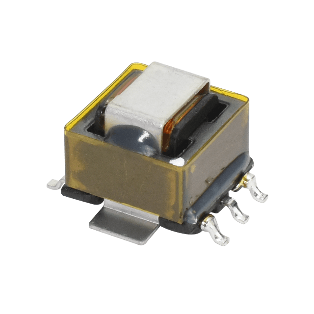
To meet these needs, you choose a Bel SCS series current sense transformer, optimized for high-frequency switching and galvanic isolation.
Selection Breakdown
| Parameter | Application Need | Bel Fuse SCS Match | Notes |
|---|---|---|---|
| Frequency | ~100 kHz | SCS series supports 50 kHz–1 MHz | Ensures fast magnetic response |
| Primary Current | Peak 10 A | SCS series rated to 10 A | Sized to avoid core saturation or thermal stress |
| Primary DCR | < 10 mΩ | ~0.7 mΩ typical | Minimizes power loss in high-side path |
| Turns Ratio | Model with 100:1 ratio selected | Converts 10 A to 0.1 A secondary current | |
| Secondary DCR | 5.5 Ω | Minimize losses. |
When designing in a Bel Fuse SCS series CST for high-side current sensing, the following calculations validate its performance within the system:
1. Determine Secondary Current
2. Calculate Burden Resistor Value
3. Estimate Power Dissipation – DCR’s
4. Estimate Power Dissipation – Burden Resistor
5. Component Margin Checks
- Burden resistor should be rated ≥ 0.25 W for thermal safety.
- CST isolation voltage must exceed system requirement (e.g., 2.5 kV min).
Why This Configuration Works
- The CST enables non-intrusive current sensing on the high-side without degrading power path efficiency.
- The 1 V output from the burden resistor fully utilizes the controller’s ADC input range, improving resolution.
- Galvanic isolation protects low-voltage control electronics from high-voltage switching transients.
- Using a transformer rather than a sense resistor avoids thermal drift, improves noise immunity, and reduces component stress.
Real-World Considerations
- In this high-side sensing configuration, careful PCB layout is essential to minimize parasitic coupling and ensure clean signal routing from the CST secondary.
- For high-reliability environments—such as server power or telecom backplanes, choosing a Bel SCS model rated for extended temperature and voltage margins ensures long-term performance.
Final Considerations for Choosing a Current Sense Transformer
Current sense transformers (CSTs) are essential components in applications where accurate AC current measurement and galvanic isolation are non-negotiable. Their ability to deliver reliable, real-time current sensing without inserting significant losses makes them ideal for high-efficiency power systems, safety-critical circuits, and noise-sensitive environments.
The strongest advantage CSTs offer is electrical isolation, protecting low-voltage control circuitry from high-voltage switching stages while minimizing common-mode noise. Their compact, passive construction further simplifies integration into dense power architectures.
However, proper device selection is critical. Designers must balance turn ratio, core material, burden resistor, operating frequency, and isolation voltage to ensure the CST performs reliably under all expected conditions. When matched correctly to the application, a CST can enhance both performance and safety without adding unnecessary complexity.
Explore Bel's CST product lineup to boost performance while ensuring safe, streamlined design.

.png)