

NEBS Standards Overview for Telecom Power and Network Equipment
When deploying power supply solutions in telecommunications environments, the importance of choosing the correct type cannot be overstated. Power supply selection is often reduced to basic parameters such as voltage and current rating, and while that approach may work in basic applications, it rarely holds up in real telecom deployments.
Telecommunication infrastructure often operates in environments where high reliability is required and conditions are not always ideal. For example, equipment can be exposed to temperature variation, electrical noise, vibration, and continuous operation while under load.
To address these challenges, engineers can rely on standards that define how equipment should behave in these conditions, with one of the most widely used being the Network Equipment-Building System (NEBS).
The Significance of NEBS Compliance in Carrier‑Grade Deployments
The origins of NEBS date back to the 1970s, when telecommunications systems were expanding rapidly. Laboratories, offices, and industrial sites all deploying telecom networks where environmental conditions could vary significantly.
During this time, telecommunications infrastructure became just as critical as power, water, and roads. With more hardware entering the market and the rapid expansion of telecoms across multiple environments, a new defining standard was needed to help engineers select appropriate and compatible systems.
To address this challenge, Bell Labs developed the NEBS, a standardized certification outlining how network equipment should behave inside a Regional Bell Operating Company (RBOC) central office. The standard is now published by Telcordia, which is owned by Ericsson.
The Functional Purpose of NEBS in Carrier‑Grade Design
The simplest explanation of NEBS’ purpose is to ensure that telecom equipment can survive and safely coexist in harsh carrier environments. It covers not only how devices work, but also how they can be implemented without impacting other systems.
Thus, the NEBS framework is built around three core principles:
- Environmental survivability: The system must be able to endure extreme physical conditions, including temperature swings, humidity, vibration, shock, and airborne contaminants.
- Safety compliance: All equipment must meet strict electrical, fire, and grounding standards to protect personnel and infrastructure from hazards that could lead to injury or service disruption.
- Network reliability assurance: The design must ensure consistent, fault‑tolerant performance so that individual component failures do not cascade and jeopardize overall network uptime.
These three principles are tightly linked, as a failure in one area can compromise the entire system.
If all equipment in a telecom system meets NEBS requirements, then everything can safely coexist within the same central office environment. This includes interaction between power systems, thermal output, electromagnetic behavior, fire safety, and vibration tolerance. The net result of this standardization is predictable and stable deployment of hardware across a variety of central office environments.
Core NEBS Documents: GR-63-CORE, GR-1089-CORE, and SR-3580
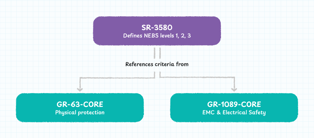
Before the various levels of NEBS compliance can be covered, we first need to look at both GR-63-CORE and GR-1089-CORE, two primary documents that define technical requirements for installations, as these are used for defining the various Levels.
- GR-63-CORE focuses on the physical environment of an installation, including temperature, humidity, fire spread, smoke behavior, vibration tolerance, earthquake tolerance, airborne contaminants, altitude, and mechanical stress.
- GR-1089-CORE focuses on electrical safety and electromagnetic behavior. This includes grounding and bonding, electrostatic discharge protection, electromagnetic emissions and immunity, and resistance to lightning and surge effects.
However, while these two documents define the required performance characteristics of installations in telecom environments, they do not define compliance levels.
NEBS compliance levels are instead defined in SR-3580, which maps deployment environments to specific subsets of requirements from GR-63-CORE and GR-1089-CORE. SR-3580 provides the framework that translates detailed technical criteria into standardized certification levels for real-world deployments.
NEBS Compliance Levels and Deployment Categories
NEBS defines three levels of compliance, each aligned with different deployment environments.
Level 1
Level 1 is the baseline, covering basic safety requirements. It is based on the safety sections of GR-63-CORE and GR-1089-CORE, and is used in environments where there is minimal risk to personnel or infrastructure, such as lab trials and early-stage deployments.
Level 2
Level 2 builds on Level 1 by tightening requirements, introducing electromagnetic compatibility constraints and partial environmental considerations. This level assumes a relatively stable environment, such as a datacenter, where some degree of robustness is required but conditions are still controlled.
Level 3
Level 3 is intended for full carrier-grade deployment. This level includes a wide range of requirements, including fire resistance, temperature and humidity extremes, vibration and seismic resilience, airflow restriction tolerance, acoustic limits, Electromagnetic compatibility (EMC) for both immunity and emissions, as well as defined behavior under fault conditions such as fan failure or partial system faults.
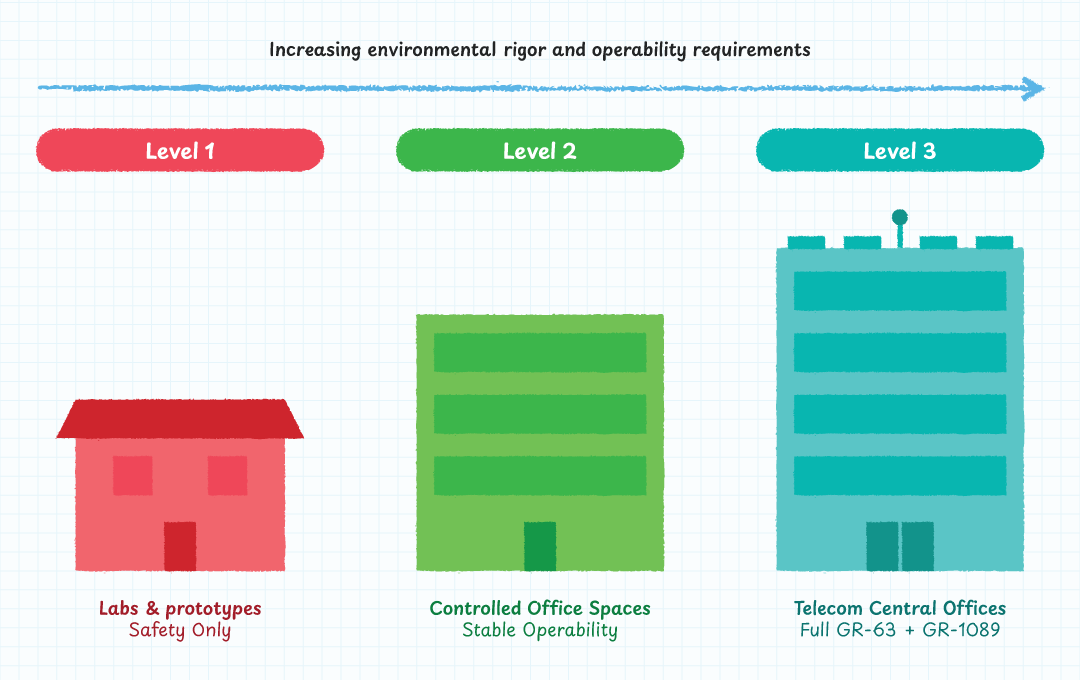
What these levels fundamentally translate to is that Level 1 applies to lab-like environments with stable hardware and minimal risk, Level 2 applies to initial deployments in relatively easy environments with moderate requirements, and Level 3 applies to carrier-grade systems where maximum reliability is required, downtime is not acceptable, and interference must be controlled.
Environmental Stress Factors Affecting NEBS Power Supply Architecture
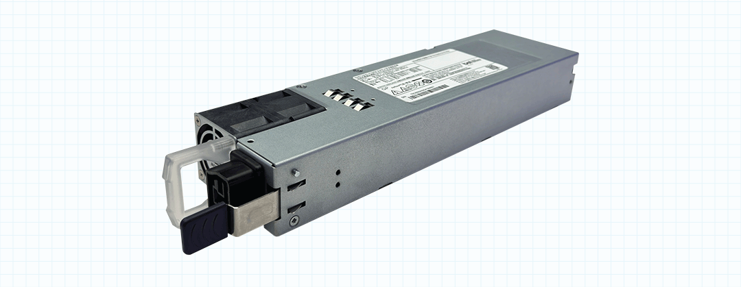
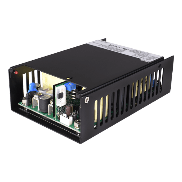
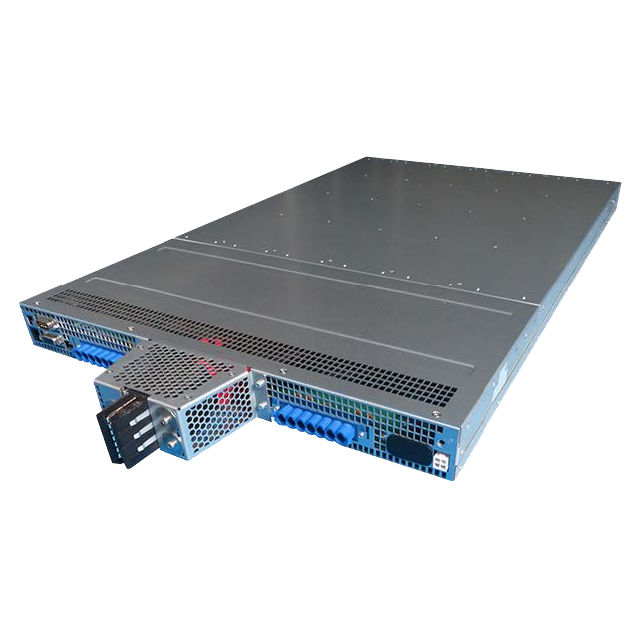
NEBS requirements apply to all components in a telecom system, including cables, racks, and active equipment. Power supplies are particularly affected because they are exposed to both electrical and thermal stress and directly influence system stability.
Thermal performance is a particularly critical factor in high-density systems where heat from one unit can affect neighboring equipment. This is especially true in datacenter-style deployments where airflow and hot air channels must be carefully managed.
In cases where predictable behavior during faults needs to be met, redundant power supplies operating in parallel can help to mitigate the risk of individual failures. Such topologies introduce additional complexity in load sharing and system design, thus making the requirements stricter on power supplies.
Safety systems must also be robust, with power supplies needing to integrate fault protection, current leak detection, and residual current detection to ensure safe operation for both equipment and personnel.
It should be noted that the use of certain mitigation and reliability techniques such as fault protection, redundant supplies, and thermal monitoring are not strict requirements laid out in NEBS standards. Rather, these techniques help a design to meet stated requirements for predictable behavior during faults (i.e. during a power fault, a backup supply will take over, or an over-current protector will disconnect).
Technical Constraints and Design Trade‑Offs in NEBS‑Certified Systems
For serious installations, meeting NEBS requirements is often non-negotiable, but doing so can introduce unavoidable trade-offs, making system integration much harder for engineers.
To start, power margins typically need to be increased to ensure reliability and safety under worst-case conditions. Such margins reduce effective power density, while additional power supplies, which are required for redundancy, increase system cost and complexity.
Protection mechanisms (such as surge suppression, filtering, and fault detection), increase both the cost and internal complexity of power supplies, while simultaneously reducing the total usable power capacity.
When stringent EMC and EMI performance is required, system costs further increase along with the greater design effort needed. Environmental conditions, such as dust and contaminants, may require sealed power supplies, removing the option for fan-assisted cooling, increasing cost and often limiting maximum power output.
Thermal and fire safety requirements introduce de-rating, which further reduces the maximum rated output of power supplies, and mechanical factors (such as vibration), require reinforced connectors and secure retention mechanisms which increases the cost of supplies.
| Constraint / Trade‑off | Technical Impact | Resulting Design Consequence |
|---|---|---|
| Increased power margins | Ensures reliability under worst‑case load and thermal conditions | Reduces effective power density; may require additional PSUs for redundancy |
| Protection mechanisms (surge suppression, filtering, fault detection) | Improves safety and fault tolerance | Raises cost and internal complexity; reduces usable output capacity |
| High EMC/EMI performance requirements | Prevents interference with adjacent telecom systems | Increases design effort, shielding requirements, and overall system cost |
| Environmental exposure (dust, contaminants) | May require sealed or hardened enclosures | Eliminates fan cooling options; limits max power output; increases cost |
| Thermal and fire safety derating | Ensures safe operation under elevated temperatures and fire‑risk scenarios | Reduces maximum rated output; requires more conservative thermal design |
| Mechanical stress (vibration, shock) | Prevents connector failure and intermittent faults | Requires reinforced connectors, retention hardware, and mechanical stiffening |
| System‑level redundancy requirements | Ensures uptime in carrier‑grade deployments | Adds cost, weight, and complexity to system integration |
Table 1: Key Technical Constraints and Design Trade‑offs in NEBS‑Certified Systems
Combine all of these factors together and one thing becomes abundantly clear; NEBS compliance can rapidly introduce design challenges, raise costs, and slow project development. However, considering that these enterprise carrier-grade applications have extreme reliability requirements and must operate in harsh environments, it is often a necessary trade off when deploying cutting-edge telecommunication systems.
Incorporating NEBS Requirements into Telecom System Architecture
To engineers who are new to NEBS, it should be understood as a system-level engineering framework that defines how telecom equipment should be designed to survive real central office environmental, electrical, and safety conditions.
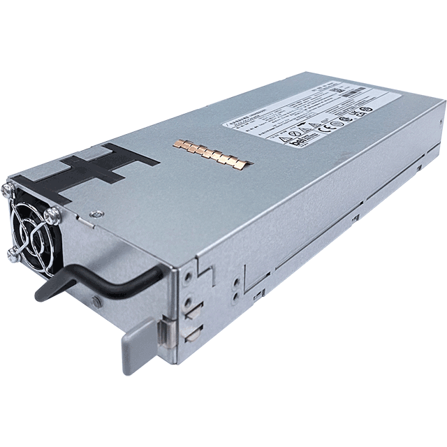
Power supplies are heavily affected by NEBS requirements due to their exposure to thermal stress, electromagnetic environments, electrical transients, and high-density deployment conditions. As such, they must be designed with reliability as a primary objective.
Designing for NEBS compliance introduces clear trade-offs, including higher cost, increased design complexity, reduced power density, and the need for additional protection and redundancy.
Thus, engineers approaching telecom systems must consider NEBS requirements during early design stages, making sure that factors like reliability are designed into the system from the start, rather than added later through costly redesigns.
Selecting the right power supply for a NEBS-compliant deployment involves more than matching voltage and current ratings. Contact a Bel applications engineer to discuss your system requirements and identify the right solution for your environment.

.png)