Being uncomfortably hot or cold may be a subjective opinion based on an individual’s feeling at any given moment. However, unlike humans, transformers, inductors, electric motors, and similar electronic devices are not subject to chill factor or heat stroke in the traditional sense. How they react is solely a consequence of their attained temperature while in service.
The Importance of Temperature Control
Electric, electronic, and electromechanical equipment is vulnerable to the effects of extreme temperature variation. The threat of potential failure looms when electrical equipment is even occasionally exposed to temperatures that exceed the designated maximum rating of its Insulation System.
Due to inefficiencies and losses, most electric and electronic components are exothermic, radiating some level of heat during normal operation. Designers and engineers are acutely aware of this and so specify appropriately rated materials that are adequate to survive maximum anticipated temperature rise along with their having the durability to remain safe and effective during the service life of their host equipment. Engineers may also consider utilizing heat sinks, forced cooling or other means to maintain acceptable temperatures during operation under various ambient conditions. But the primary means of failure prevention lies with having specified an adequate insulation system.
The safe and reliable operation of dry type transformers depends upon the integrity of their Insulation Systems. If the insulation supporting dielectric separation between the main’s input potential and any proximate low voltage secondary winding fails, a safety hazard or fault condition is almost certain to occur. Thus, the long-term safety and reliability of dry-type, convection cooled transformers is contingent on specifying an appropriately rated Insulation System, based on the temperature rise of the transformer and the environment in which the transformer operates.
Insulation Systems and Thermal Ratings
As defined by Underwriters Laboratory (UL) standard 1446, an Insulation System is: "unique intimate combination of two or more insulating materials used in electrical equipment."
Numerous combinations of materials that are physically proximate or applied in direct contact with one another are tested and evaluated using a long-term thermal aging process and are then categorized under a defined, Insulation System Class Rating.
These tests confirm the insulation materials do not interact with each other in such a way as to alter or degrade any of the materials when combined in a single use.
Within the UL 1446 standard, insulation materials are grouped as either: Major or Minor Components.
- Major Components are those components of an insulation system relied upon to prevent the risk of shock or fire.
- Minor Components of an insulation system address physical separation / interaction or thermal conduction capacities and are not relied upon to prevent the risk of shock or fire.
UL Insulation Ratings
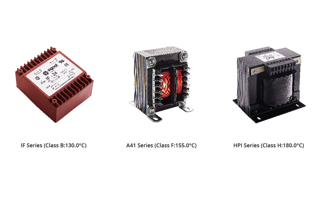
The UL’s Insulation System Class Rating sets down a system’s maximum safe, hot-spot operating temperature. Class letter designations along with their numeric, Celsius, maximum temperature ratings are as follows:
105 “A”, 120 “E”, 130 “B”, 155 “F”, 180 “H”, 200 “N”, 220 “R” and 240 “S”, >240 °C.
To ensure long term reliability, the maximum continuous temperature-rise on transformer coil windings as obtained empirically by the Change of Resistance Method should not exceed the following levels:
| UL Class | Max Δt (in °C) |
|---|---|
| 105 (A) | 70.0 |
| 120 (E) | 80.0 |
| 130 (B) | 95.0 |
| 155 (F) | 115.0 |
| 180 (H) | 135.0 |
| 200 (N) | 150.0 |
| 220 (R) | 165.0 |
| 240 (S) | >240.0 |
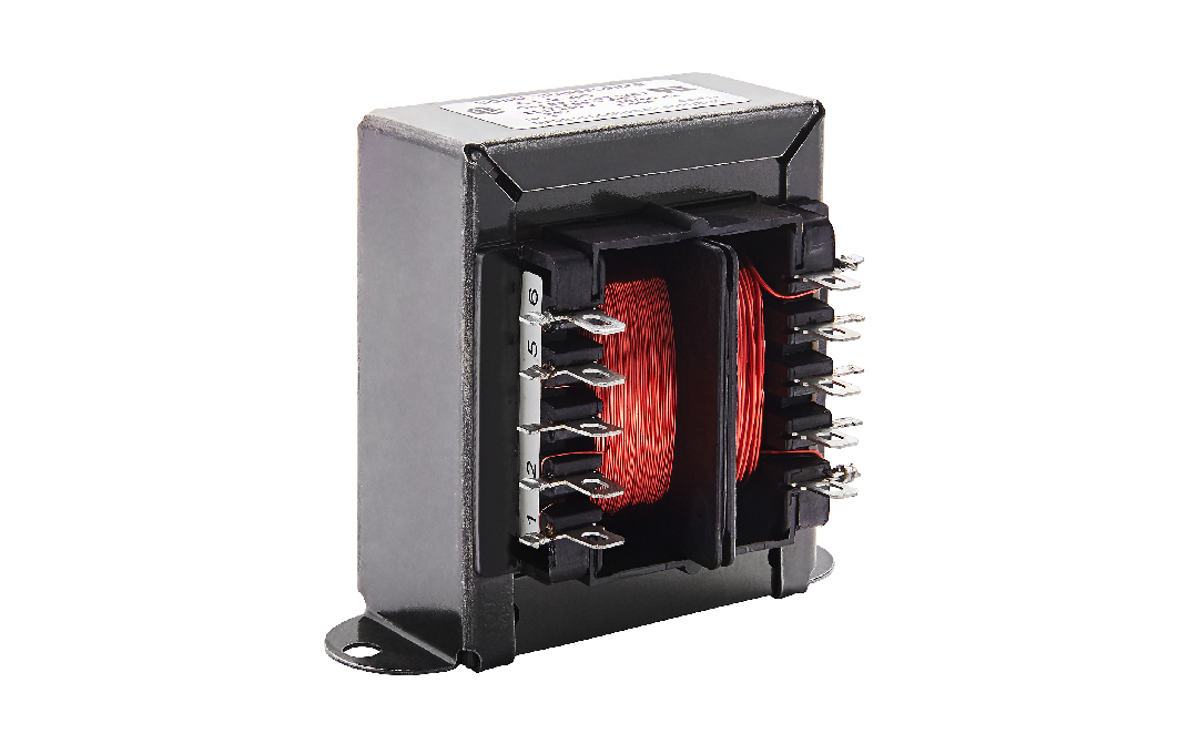
Within transformer components, heat is from losses generated in the current carrying conductors, (typically copper wire) and the iron core material. Copper or aluminum conductors are in direct contact with the insulating materials, resulting in direct thermal transfer. The conductors are typically sandwiched between layers of insulation films and are the prominent heat source impacting the insulation system’s materials.
When conducting qualification tests on transformer components, verification of the maximum temperature rise of the conductors, while operating at maximum rated load and at the anticipated environmental conditions is essential.
The method specified in the UL and IEC standards for verifying the temperature rise of coil windings is the Change of Resistance formula.
Change of Resistance Formula -
Δt = R/r (k + t1) - (k + t2)
where:
- Δt is the temperature rise.
- R is the D.C. resistance of the coil at the end of the test.
- r is the D.C. resistance of the coil at the beginning of the test.
- k is 234.5 for copper and 225.0 for aluminum.
- t1 is the ambient/wire temperature in degrees C at the beginning of the test.
- t2 is the wire temperature in degrees C at test conclusion.
IEC Insulation Systems
The International Electrotechnical Commission, (IEC) standard 60085 contains specifications and details for Insulation Systems utilized in electrical equipment qualified to IEC standards. The IEC standard for transformers, 61558-1 specifies four insulation types that may be utilized independently or in combination in transformer construction.
- Basic Insulation: Insulation applied to hazardous live parts to provide basic protection against electrical shock due to inadvertent contact.
- Supplementary Insulation: Independent insulation applied in addition to basic insulation to provide protection against shock in the event of failure of the basic insulation.
- Double Insulation: Insulation comprising basic insulation plus supplementary insulation.
- Reinforced Insulation: A single layer insulation system applied to electrically live parts which provides a degree of protection against electric shock quivalent to “Double Insulation”.
The level of insulation is typically selected based on the application, working voltage, dielectric levels, anticipated operating temperature and service life, weighed against the cost of manufacture.
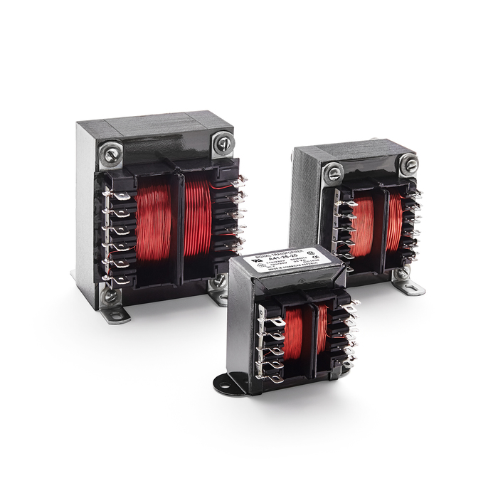
As a practical example of a design that assures long term reliability and safety, EcoTran Series transformers incorporate a UL 1446 Class F 155 C insulation system and are constructed using IEC type Double Insulation offering high dielectric strength and shock hazard protection.
The construction of these transformers showcases how a high-level insulation system can be employed in a versatile and low cost design.
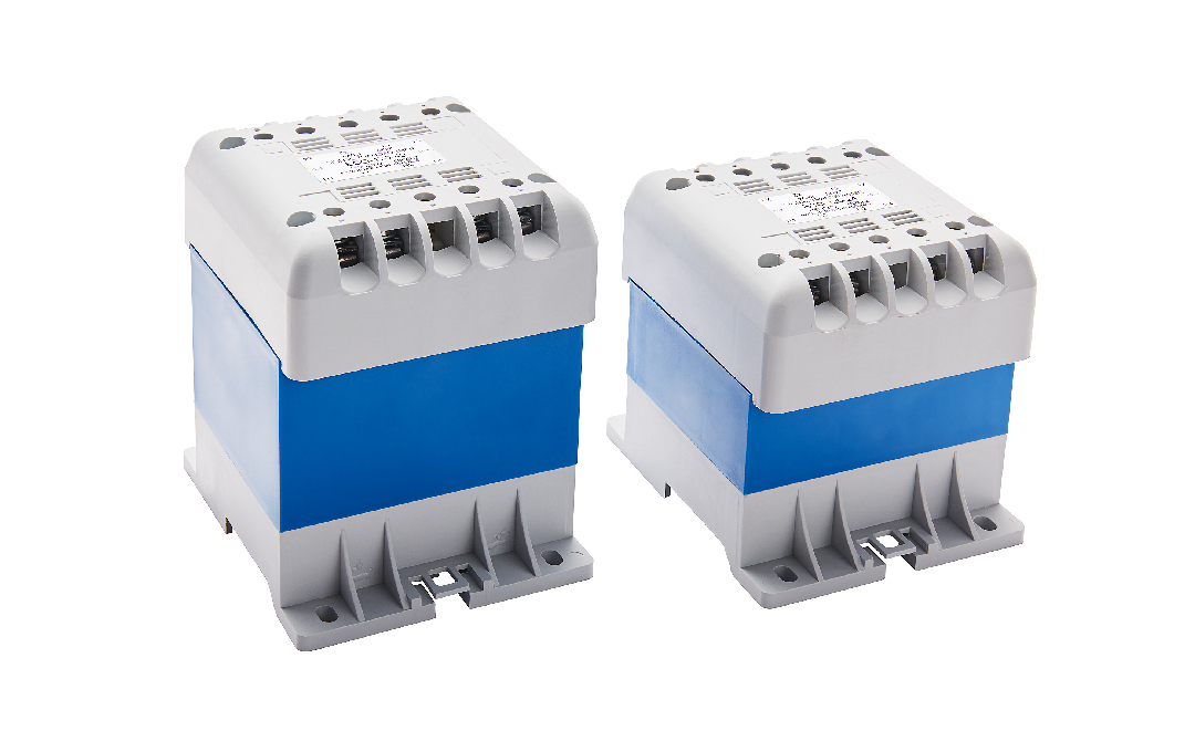
Explore Bel’s extensive selection of UL-rated transformers to ensure your application meets the highest standards of safety and reliability.