
Many AC-DC power supplies and DC-DC converters have output power ratings that can vary significantly depending on the type of cooling provided. The two most common methods of cooling a power supply are Convection cooled and Forced air cooling. “Convection air cooling” usually refers to situations where a power supply or converter is cooled by the prevailing ambient air temperature, next to the power supply, without forced-air-flow from fans or blowers. The supply may also be cooled by a fan mounted in or on the AC supply or be cooled by a system fan. Many times the power supply specification has two output power ratings, the “convection cooled” (still-air) power rating will be less than the “forced-air cooling” rating.
Airflow Ratings and Fan Sizing
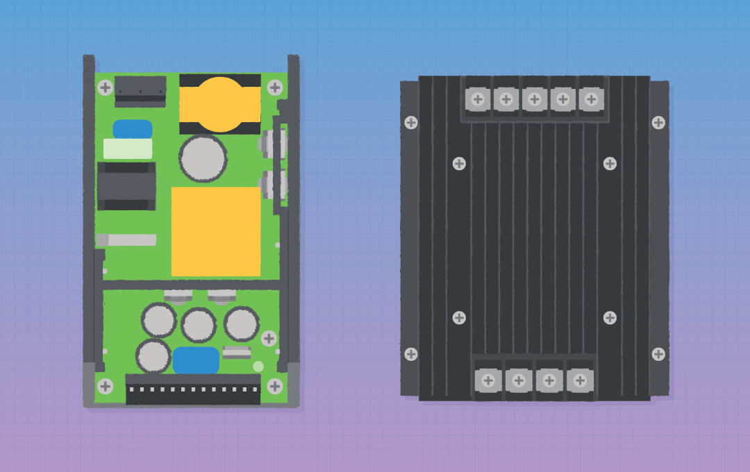
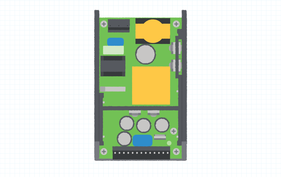
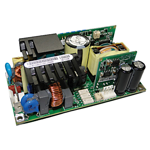
The power supply pictured, the ABC400 in Figure 1 is a U channel type supply. The size is 3” x 5” x 1.5” It has an output power rating of 400 watts with 200 LFM/1.0 m/s of forced air flow at a max ambient temperature of 50 C. The supply also has a “convection cooled” rating of 120 watts. The datasheet for this power supply indicates that for “forced-air-cooled” applications, 200LFM/1.0 m/s (Meters per Second) must be provided by the user. 1.0 m/s equals 196.85 LFM (Linear Feet per Minute).
See conversion factors below.
Sometimes fan vendors will give two ratings for airflow, one rating in LFM and the other rating in CFM. Most of the time, fans are rated in CFM (or Cubic Feet per Minute) of air “Volume” flow. For the power supply specification for the above supply in Figure 1, 200 LFM of airflow is required to get full load out at an ambient temperature of 50C. So, the question is what size fan do you need to provide 200 LFM of air “Velocity” flow for the above application in Figure 1? Generally, the power supply is cooled by directing the air flow along its longest dimension, for example, from the input connector end to the output connector end. This would be the case for the U channel supply pictured above in Figure 1.
Airflow Requirements in DC to DC Converters
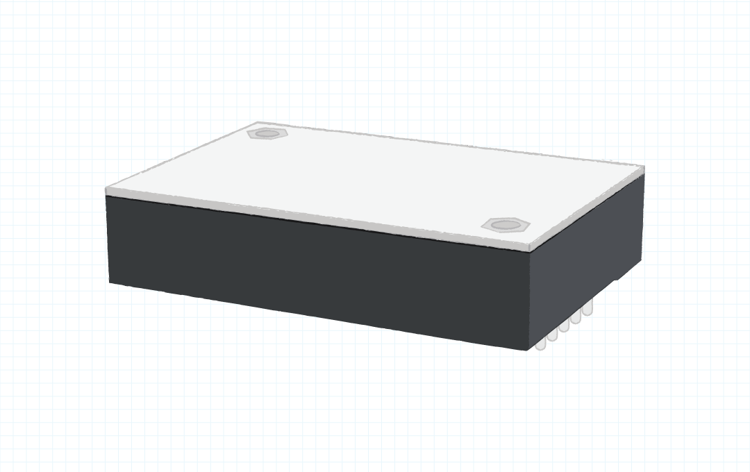
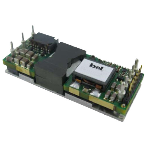
Airflow for a U channel supply would never be blown across the U channel. However, many Dc-to-Dc converters, like the one in Figure 2, will require forced airflow across the converter and not from input to output. Always check the specification for the specified amount of airflow needed and the direction of the airflow.
The most common method for determining the required fan size is to first determine the height and width for the opening or port through which the air will flow through the power supply. In the instance of Figure 1, the U channel power supply is 3.0” wide, 1.5” high and 5.0” long. The supply’s width times its height is the area of the inlet port for forced air cooling of the supply.
First, the width and height dimensions need to be converted from inches to feet by dividing by 12”. Thus, . So, the minimum “Area” of the port through which the air must flow to cool the power supply is 0.0312 square feet.
Calculating Fan CFM Rating
The formula for determining the CFM (volume) rating of the fan, when the required LFM (velocity) is known, is as follows.
Therefore, in the Figure 1 example:
In the metric world, fans are sometimes rated in "/hr" (Cubic Meters per Hour) and the air velocity is rated in “m/s” (Meters per Second). The following Metric to English Conversion factors may be useful.
Some fans and power supplies have dimensions in mm (millimeters).
Note that 1 inch = 25.4 mm, and 1 mm = 0.04”
| LFM | CFM | M/S |
|---|---|---|
| 100 | 3.12 | 0.51 |
| 150 | 4.68 | 0.76 |
| 200 | 6.25 | 1.02 |
| 250 | 7.8 | 1.27 |
| 300 | 9.36 | 1.52 |
| 350 | 10.92 | 1.78 |
| 400 | 12.48 | 2.03 |
Backpressure Considerations in Fan Selection
Fans are rated in CFM based upon the expected free flow of the air coming from them. This rating is based on no back pressure.
Back pressure is an obstruction to airflow. Back pressure can be caused by fan safety screens, small exhaust opening sizes, and large components such as capacitors or heat sinks, etc. In a real-world application, there will always be some back pressure as well as some obstructions. To ensure the least amount of back-pressure, it is best to have the exit ports in the enclosure about 1.5 times the area of the minimum entry port. In most applications there are other heat loads and components that can obstruct the path or free flow of the cooling air. It is therefore wise to select a fan with a higher rating than is calculated.
In the Figure 1 example, the calculations show the minimum fan rating of 6.25 CFM is required, but a 10 CFM rated fan or larger may be a better choice.
Another good suggestion is to try to use a larger fan running at a slower speed. This larger fan running at a slower speed may deliver the same airflow as a smaller fan running at a higher speed. The larger fan running at a slower speed will have a higher MTBF rating and should be quieter in the end application. Fan speed control circuits are often used to control the amount of airflow.
Since most fans have round air outlets and square mounting patterns, the airflow from the fan may require ducting or baffling within the end-product's enclosure to direct the cooling air to the high-power devices, including the power supply.
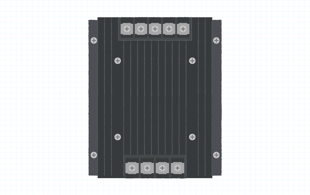
The same process would be used to determine the correct fan rating for AC-DC power supplies or DC-DC converters (with or without heat sinks) that require forced-air-cooling. When heat sinks are used, (see figure 3 below) always direct the air flow in the same direction as the spaces between the fins of the heat sink. The airflow should never be directed perpendicular to the fins.
The Importance of Thermal Testing
In all applications the system must be tested with the selected fan and all other devices in place to confirm that the power supply or converter, and the load it drives, do not exceed their maximum operating temperature under worst case conditions (maximum ambient inlet air temperature, worst case output loading, airflow obstructions, etc.). If problems are observed, a higher CFM rated fan, a higher fan speed, or dual fans may be required.
During the initial design phase, if time allows and the tools are available, modeling of the complete system may be done. Flotherm is a modeling tool that is widely used to model airflow in a system.
Modeling gives a good idea of what should be expected during the prototype testing stage. Depending on what solution is being used in the application, testing of the final solution can become very involved and time consuming. If the solution is a 1U style box (Pizza Box), usually the system is already configured (except for the option of a mezzanine or daughter card). When the solution is a multi-board chassis, testing can become much more involved, especially if the system can be sold with a minimally populated board configuration. This could require thermal testing with empty card slots, cards in different slots, and a fully populated chassis. The system should have filler plates and/or filler blank boards for the missing cards.
Ensuring Efficient Airflow
Remember, air is like current, it takes the path of least resistance. Whatever the application may be, it needs to be tested thermally. A good idea is to place thermocouples on critical components to ensure that component temperature ratings are not exceeded.

.png)